Image capturing apparatus, imaging circuit, and image capturing method

a technology of image capturing and image data, which is applied in the field of image capturing apparatuses, imaging circuits, and image capturing methods, can solve the problems of increasing data transfer load, increasing the number of pixels, and increasing the load of processing imaging signals, so as to reduce the time for reading and writing image data from and in the memory, and processing the input image data is simple and easy.

Inactive Publication Date: 2007-09-27
SONY CORP
View PDF12 Cites 24 Cited by
  • Summary
  • Abstract
  • Description
  • Claims
  • Application Information

AI Technical Summary

Benefits of technology

[0017] Embodiments of the present invention are made in view of such disadvantages. It is desirable to provide an image capturing apparatus allowing a high-speed image capturing operation by reducing the time for reading and writing image data from and in an internal memory.
[0018] In addition, it is also desirable to provide an imaging circuit allowing a high-speed image capturing operation by reducing the time for reading and writing image data from and in an internal memory.
[0019] Furthermore, it is desired to provide an image capturing method allowing a high-speed image capturing operation by reducing the time for reading and writing image data from and in an internal memory.
[0022] In the image capturing apparatus according to the embodiments of the present invention, the image data to be read out from and write in the memory may be compressed in a procedure before the signal processing section performs the image quality correction operation on the captured image data. Thus, the time for reading and writing the image data from and in the memory is reduced. In addition, the compressed image data to be temporarily stored in the memory may be obtained by detecting the maximum and minimum values of the pixel data in block and the position thereof in the block and then quantizing the results of subtracting the minimum value from each value of the pixel data in the block. Thus, the input image data can be compressed by simply and easily processing the input image data in an integrated fashion. Furthermore, since the constant word length employed in the quantization of the data allows a fixed length compression encoding, the reading out and writing of the compressed image data from and in the memory are controlled more easily. Thus, the entire processing load and the data transfer load are reduced, which allows the high-speed image capturing operations.

Problems solved by technology

In particular, an increase in the number of pixels of imaging devices leads to an increase in a load for processing imaging signals.
In particular, as the number of pixels of imaging devices and the size of the RAW data increase, a data transfer load increases, which undesirably requires a longer time for writing and reading out data in and from a memory.
Accordingly, an attempt to decrease an amount of time for a recording operation requires an increase in the bus band by setting a transmission frequency higher or the like, which undesirably increases a cost of the apparatus.
Additionally, an increase in the number of pixels undesirably leads to an increase in a capacity of a memory storing the RAW data.
If a variable-length coding method is employed as the compression method, a bus band necessary for the transfer may not be kept constant, which undesirably complicates the processing and prevents an advantage of reducing the bus band from being provided.

Method used


Image

  • Image capturing apparatus, imaging circuit, and image capturing method
  • Image capturing apparatus, imaging circuit, and image capturing method
  • Image capturing apparatus, imaging circuit, and image capturing method

Examples


first embodiment

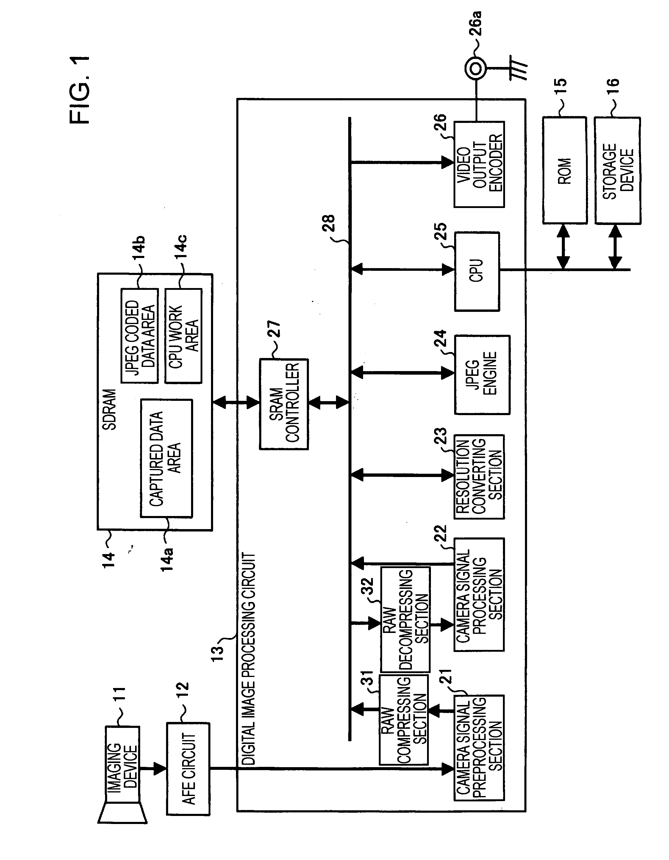
[0035]FIG. 1 is a block diagram showing a configuration of an image capturing apparatus according to a first embodiment of the present invention.

[0036] An image capturing apparatus shown in FIG. 1 has imaging devices 11, an AFE (analog front end) circuit 12, a digital image processing circuit 13, an SDRAM (synchronous dynamic random access memory) 14, a ROM (read only memory) 15, and a storage device 16. In addition, the digital image processing circuit 13 includes a camera signal preprocessing section 21, a camera signal processing section 22, a resolution converting section 23, a JPEG (joint photographic experts group) engine 24, a CPU (central processing unit) 25, a video output encoder 26, and an SDRAM controller 27, which are connected to each other through an internal bus 28.

[0037] Furthermore, in addition to those known configurations, the digital image processing circuit 13 according to the embodiment includes an RAW compressing section 31 and an RAW decompressing section ...

second embodiment

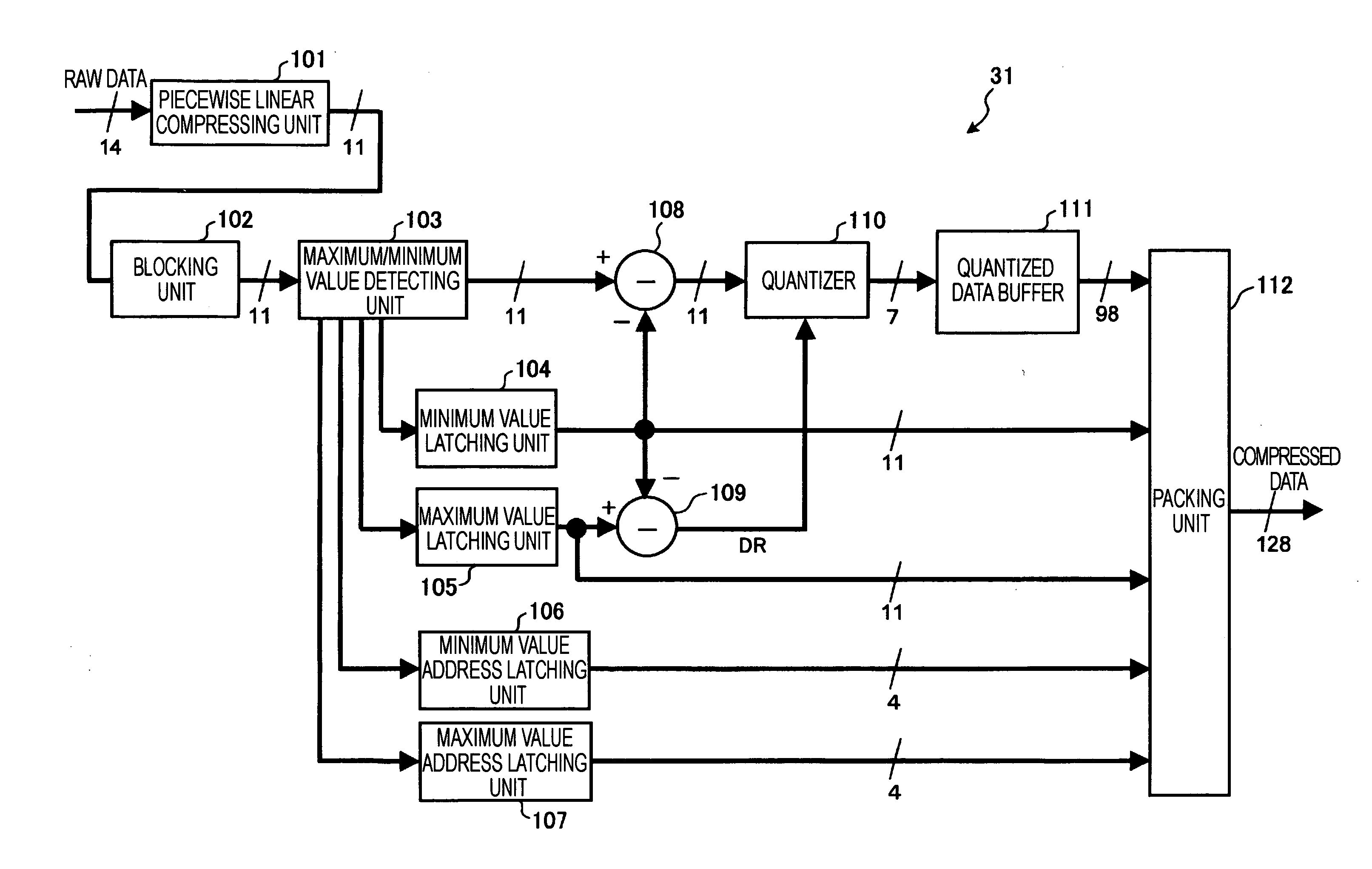
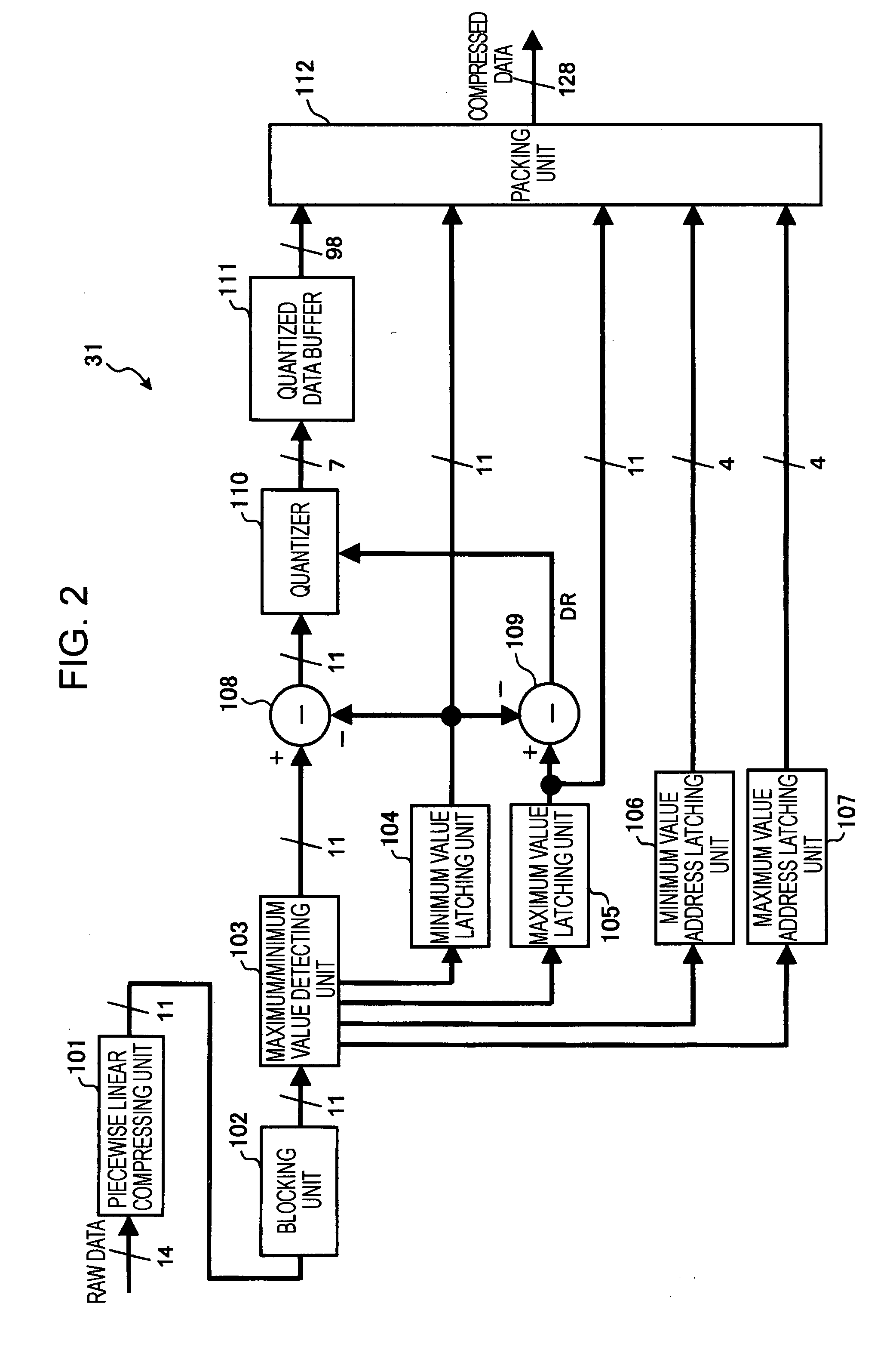
[0124]FIG. 7 is a diagram showing a structure of compressed data output by an RAW compressing section in an image capturing apparatus according to a second embodiment of the present invention.

[0125] When a quantization step size is set at a power of two in the above-described compression method, a quantizer may be constituted by a bit shifter. In such a case, a shift amount indicates a dynamic range of the block. In addition, it is obvious that all bits of the value obtained by quantizing a maximum value in the block are 1. Thus, a decompressing side can determine quantized data for the maximum value based on the shift amount instead of an absolute value of the maximum value and decompress the quantized data.

[0126] Accordingly, as shown in FIG. 7, compressed data contains the shift amount (at least 3 bits in the above-described operation example) employed by the quantizer instead of the maximum value (11 bits). This can reduce the number of bits of the data to be contained in the ...

third embodiment

[0128]FIG. 8 is a diagram showing a structure of compressed data output by an RAW compressing section in an image capturing apparatus according to a third embodiment of the present invention.

[0129] Each of the above-described embodiments shows an example in which RAW data is divided into blocks on a line-by-line basis and compressed. Application of the above compression / decompression method allows the RAW data to be divided into blocks for each rectangular area across a plurality of lines. For example, since pixel data are sequentially scanned in a case where imaging devices, such as CMOS sensors, capable of scanning all pixels (performing progressive scan) are used, a correlation between the pixel data in the vertical direction becomes stronger. Thus, even if the pixels in the rectangular area are gathered in a block, image-quality-degradation-free compression can be performed.

[0130] For example, FIG. 8 shows an example of compressed data obtained when pixel data of the same colo...


PUM


Abstract

An image capturing apparatus for capturing an image with solid state imaging devices may include a compressing section, a memory, a decompressing section, and a signal processing section. The compressing section may compress digitalized data of an image captured with the solid state imaging devices. The memory may temporarily store the compressed image data that is compressed by the compressing section. The decompressing section may decompress the compressed image data that is read out from the memory. The signal processing section may perform an image quality correction operation on the image data decompressed by the decompressing section. The compressed image data may contain a maximum value and a minimum value of pixel data in a block, information regarding positions of the maximum value and the minimum value in the block, and quantized data.

Description

CROSS-REFERENCE TO RELATED APPLICATIONS [0001] This application claims priority from Japanese Patent Application No. JP 2006-050170 filed in the Japanese Patent Office on Feb. 27, 2006, the entire content of which is incorporated herein by reference. BACKGROUND OF THE INVENTION [0002] 1. Field of the Invention [0003] The present invention relates to image capturing apparatuses, imaging circuits, and image capturing methods for capturing images with solid state imaging devices. In particular, the present invention relates to an image capturing apparatus that temporarily stores image signals resulting from an image capturing operation and processes the image signals, an imaging circuit suitable for such a configuration, and an image capturing method. [0004] 2. Description of the Related Art [0005] Recently, the use of imaging capturing apparatuses, such as digital still cameras and digital video cameras, capable of capturing images with solid state imaging devices and of storing the c...

Claims


Application Information

Patent Timeline
Patent Type & Authority Applications(United States)
IPC IPC(8): G06K9/36H04N5/232H04N5/335H04N7/26H04N19/00H04N19/136H04N19/176H04N19/196H04N19/423H04N19/85H04N19/90H04N19/91H04N19/98H04N101/00
CPCH04N5/335H04N5/772H04N5/775H04N5/85H04N19/98H04N9/7921H04N9/8047H04N2101/00H04N2201/0084H04N5/907H04N25/00
Inventor KATO, FUMIAKINAKAJIMA, KEN
Owner SONY CORP
Why Eureka
Try Eureka