Ductile cast iron scroll compressor

a scroll compressor and ductile cast iron technology, applied in the direction of machines/engines, rotary/oscillating piston pump components, liquid fuel engines, etc., can solve the problems of increasing the wear between the scroll members, not being suited for more severe operating conditions, and high-capacity compressors operating under increasingly severe conditions. , to achieve the effect of strong and durable and severe operating conditions

Inactive Publication Date: 2007-09-27
SCROLL TECH
View PDF36 Cites 2 Cited by
  • Summary
  • Abstract
  • Description
  • Claims
  • Application Information

AI Technical Summary

Benefits of technology

[0009] In the disclosed examples, the scroll member is relatively strong and durable. This allows the scroll compressor to withstand more severe operating conditions associated with high capacity compressor designs.

Problems solved by technology

Higher capacity compressors operate under increasingly severe conditions, such as higher forces and increased wear between the scroll members.
Use of current materials for the scroll members has proven successful in many compressors but may not be suited for more severe operating conditions.
For example, under extreme operating conditions, the scroll members may break or wear excessively.

Method used


Image

  • Ductile cast iron scroll compressor
  • Ductile cast iron scroll compressor
  • Ductile cast iron scroll compressor

Examples


Embodiment Construction

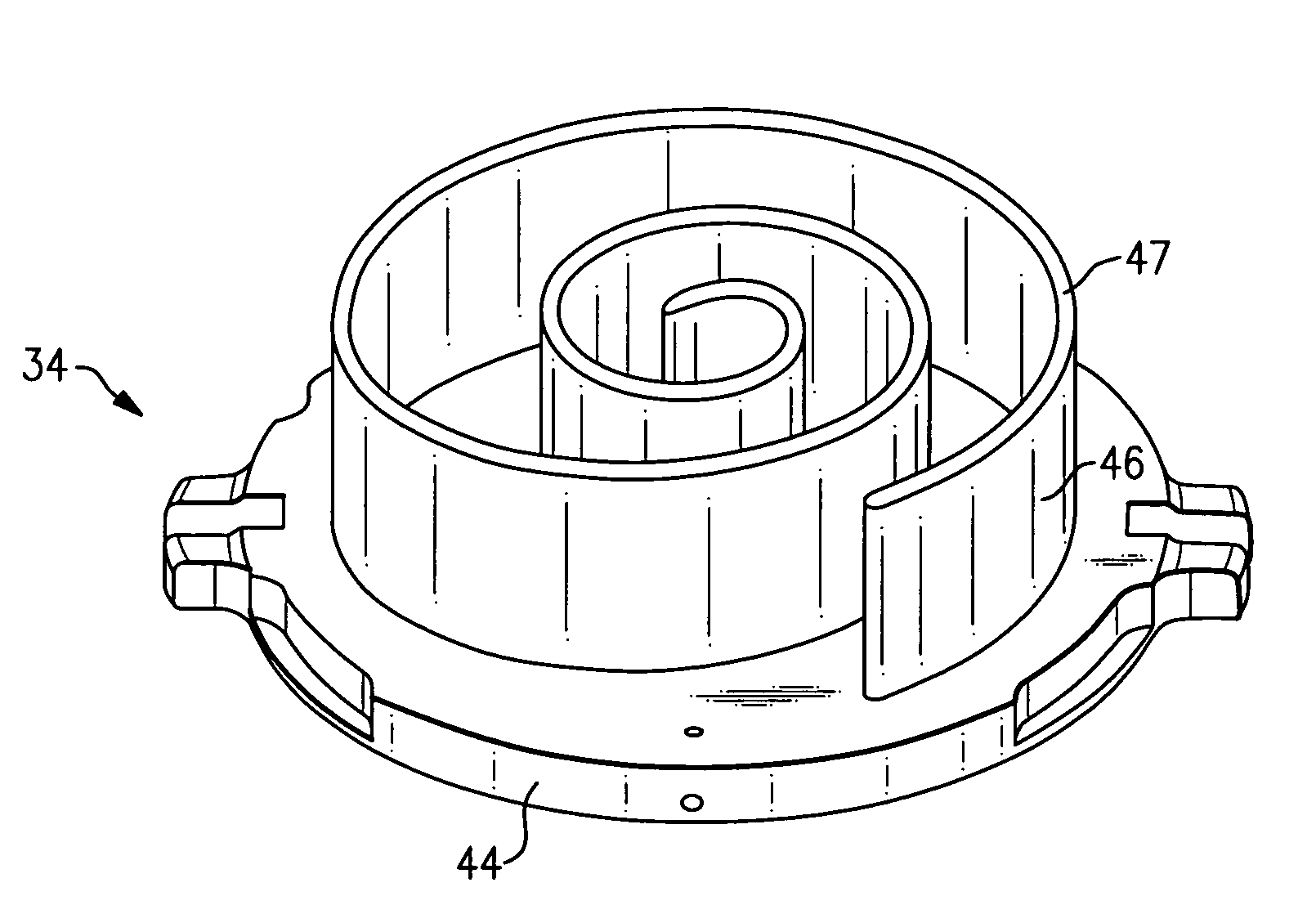
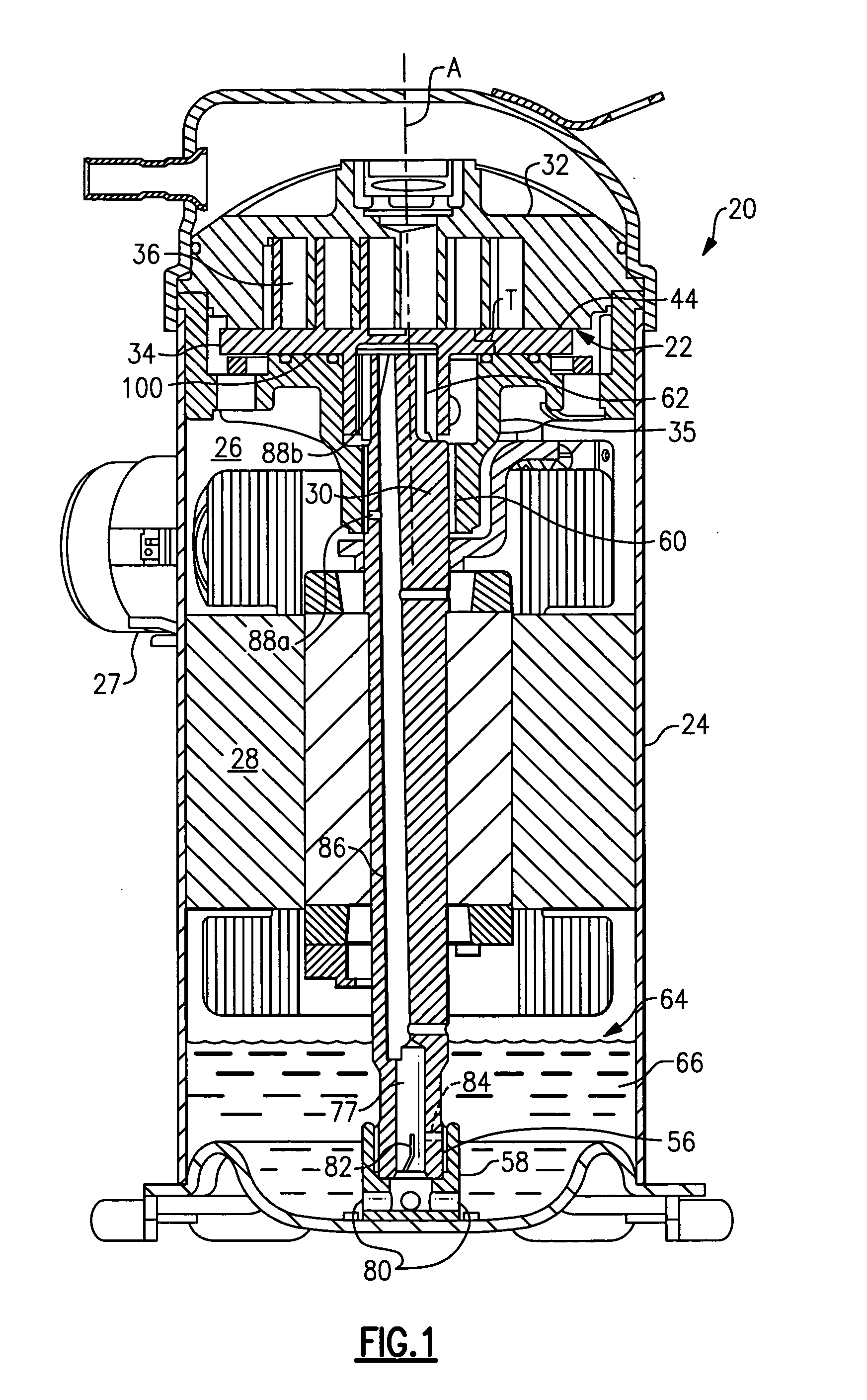
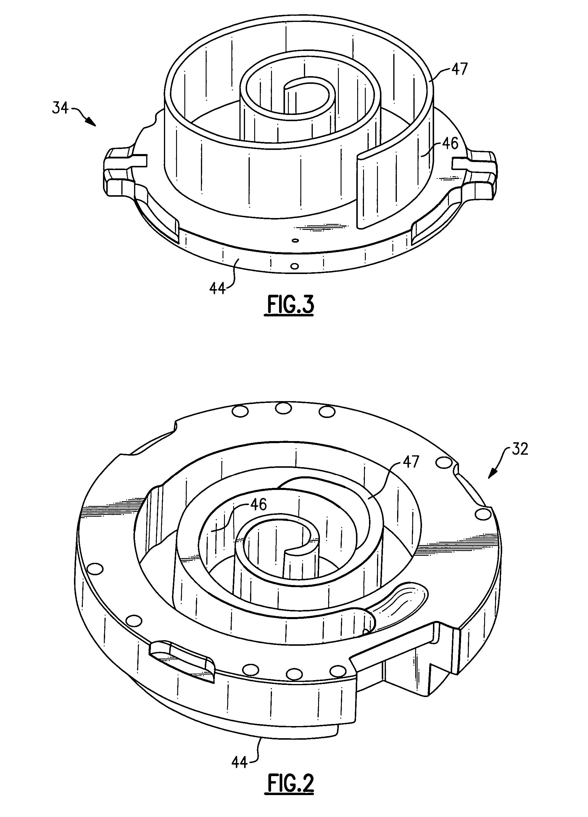
[0017]FIG. 1 shows a scroll compressor 20. As shown, a compressor pump set 22 is mounted within a sealed shell 24. A suction chamber 26 receives a suction refrigerant from a tube 27. As can be appreciated, this refrigerant can circulate within the chamber 26, and flows over an electric motor 28. The electric motor 28 drives a shaft 30 that defines an operative axis A for the compressor 20. The compressor pump set 22 includes a non-orbiting scroll 32 and an orbiting scroll 34 that is supported on a crankcase 35. As is known, the shaft 30 drives the orbiting scroll 34 to orbit relative to the non-orbiting scroll 32 to compress the refrigerant.

[0018] In this example, the shaft 30 is supported within the compressor 20 by three different bearing bushings. The bottom of the shaft 30 includes a first bearing bushing 56, or lower bearing bushing, which is received in a bearing hub 58. A second bearing bushing 60, or crankcase bearing bushing, is located farther toward the top of the compre...


PUM

PropertyMeasurementUnit
microstructureaaaaaaaaaa
extreme pressureaaaaaaaaaa
viscosityaaaaaaaaaa

Abstract

A scroll compressor includes a scroll member having a base and a generally spiral wrap that extends from the base to define a portion of a compression chamber. The scroll member is made of a cast iron material comprising a microstructure having graphite nodules.

Description

BACKGROUND OF THE INVENTION [0001] This application relates to scroll compressors and, more particularly, to a scroll compressor member with improved strength and durability. [0002] Scroll compressors are becoming widely utilized in refrigerant compression systems. As known, a pair of scroll members each has a base with a generally spiral wrap extending from the base. Typically, one scroll is non-orbiting and the other scroll orbits relative to the non-orbiting scroll. The orbiting scroll contacts the non-orbiting scroll to seal and define compression chambers. When the orbiting scroll member is caused to orbit relative to the other, the size of the compression chambers decreases toward a discharge port, and refrigerant is compressed. [0003] One example refrigerant compression system includes an air conditioning or other environmental conditioning system. As is known, a compressor compresses a refrigerant and sends the refrigerant to a downstream heat exchanger, and typically a cond...

Claims


Application Information

Patent Timeline
Patent Type & Authority Applications(United States)
IPC IPC(8): F01C1/02F01C1/063
CPCF01C21/02F04C18/0215F04C23/008F05C2251/14F04C2230/91F05C2201/0439F05C2201/0442F04C29/025
Inventor SUN, ZILI
Owner SCROLL TECH
Why Eureka
Try Eureka