Wireless Communication System and Radio Station

Inactive Publication Date: 2007-09-27
PANASONIC CORP
View PDF6 Cites 35 Cited by
  • Summary
  • Abstract
  • Description
  • Claims
  • Application Information

AI Technical Summary

Benefits of technology

[0044] According to the invention, there can be provided the wireless communication system capable of decreasing the effect of radio interference on a different wireless station using the same frequency band and preventing information from le

Problems solved by technology

However, geographic conditions and motion of human beings are complicated in the actual radio propagation space and thus not only the transmission path of a wireless channel fluctuates irregularly with time (which will be hereinafter referred to as time fluctuation), but also a plurality of wireless stations using the same frequency band in the limited radio propagation space can be an interference source with each other.
That is, it is practically difficult for each wireless station to control its communication area strictly and thus there is a possibility that radio interference more than stipulated may be received, which causes the errors on the transmission path to occur for largely degrading the transmission quality.
Thus, wireless communications also have a fundamental defect that there is a fear of information leakage as the communication descript

Method used


Image

  • Wireless Communication System and Radio Station
  • Wireless Communication System and Radio Station
  • Wireless Communication System and Radio Station

Examples


first embodiment

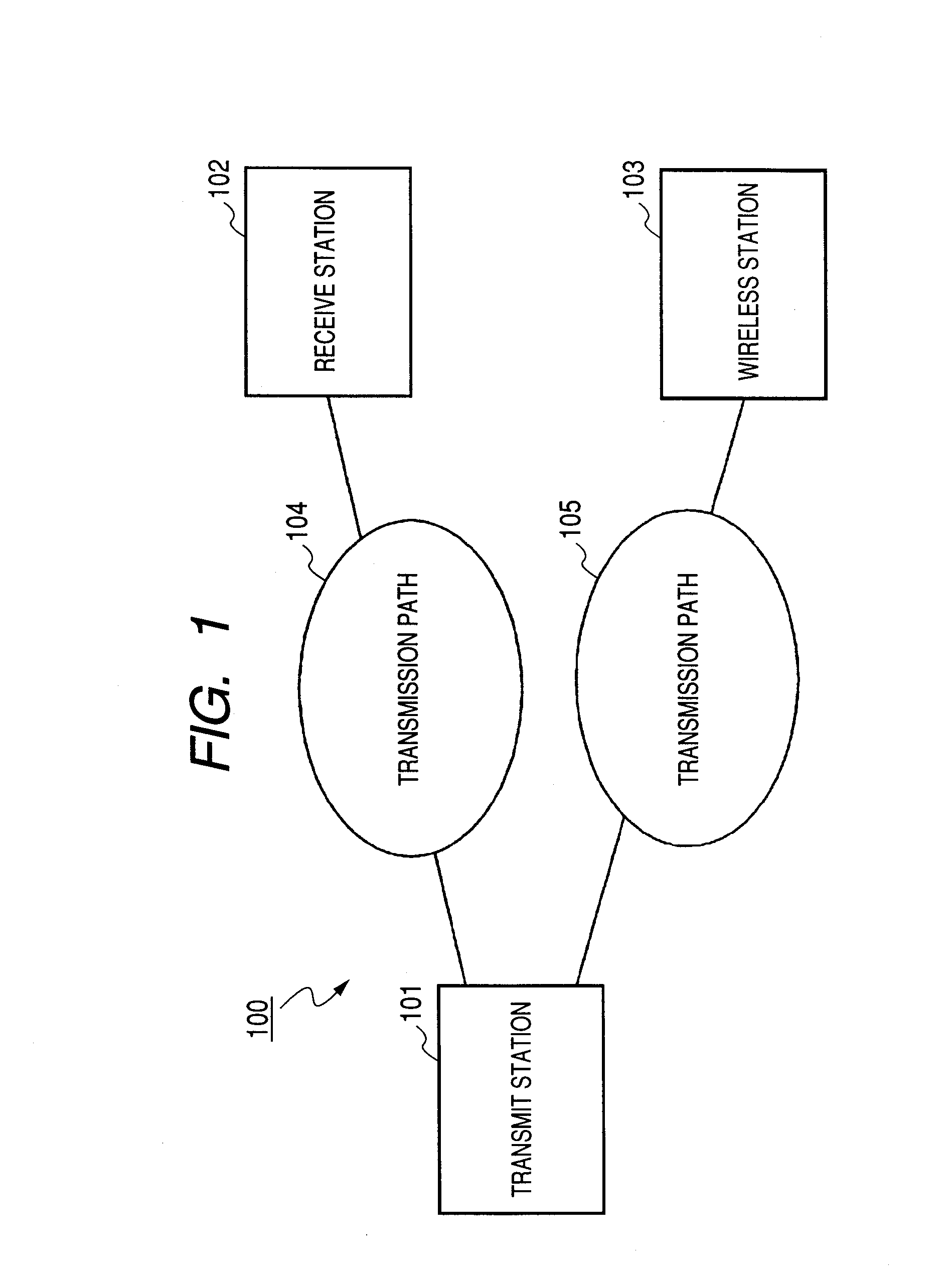
[0067]FIG. 1 is a diagram to show the schematic configuration of a wireless communication system to describe a first embodiment of the invention.

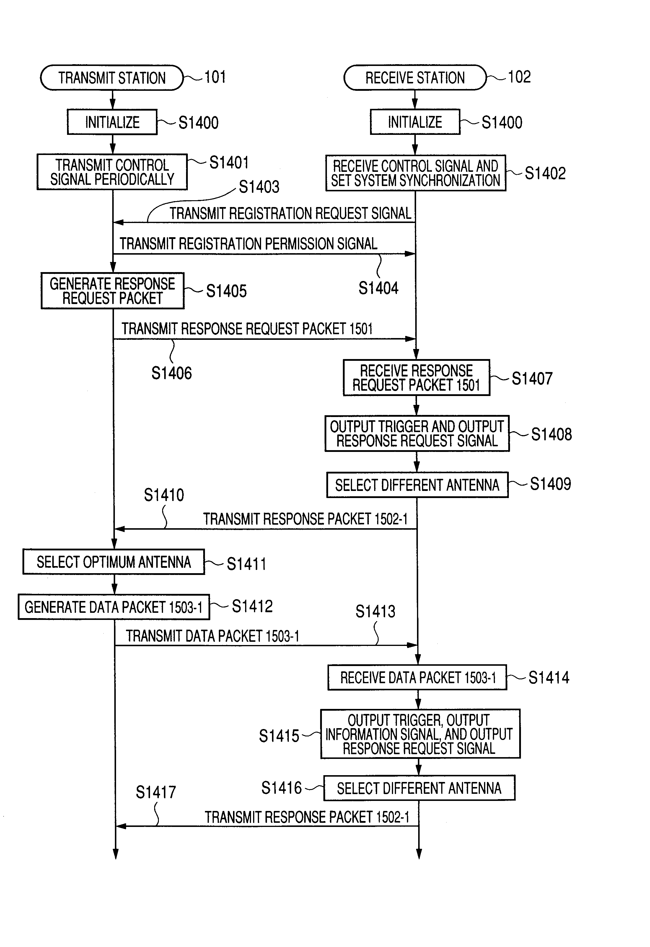
[0068] A wireless communication system 100 shown in FIG. 1 includes a wireless station 101 (which will be hereinafter referred to as transmit station 101), a wireless station 102 (which will be hereinafter referred to as receive station 102), and a wireless station103. The transmit station 101 is an access point of a wireless LAN, etc., for example. The receive station 102 and the wireless station 103 are mobile wireless terminals of mobile telephones, LAN cards, etc., for example. The transmit station 101, the receive station 102, and the wireless station 103 exist at the same time in the communication area of the transmit station 101. The transmit station 101, the receive station 102, and the wireless station 103 can conduct wireless packet communications with each other according to the communication area provided by the transmit statio...

second embodiment

[0134] A wireless communication system of a second embodiment has a configuration wherein transmit power of a transmit packet transmitted from the transmit station 101 is controlled based on the quality of the transmission path 104 in the wireless communication system of the first embodiment. Only differences from the configuration described in the first embodiment will be discussed below:

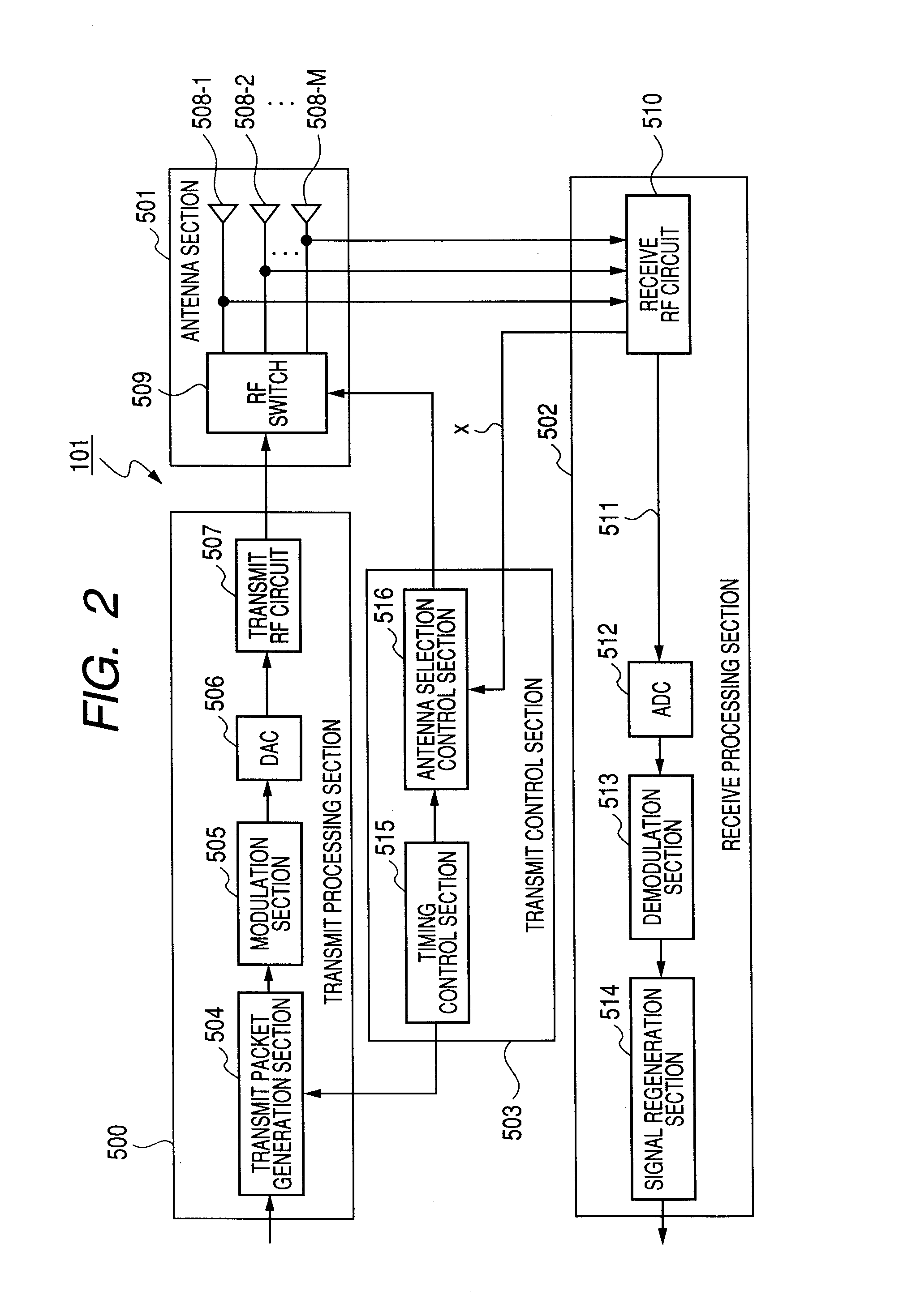
[0135]FIG. 8 is a diagram to show the schematic configuration of a transmit station of the wireless communication system to describe the second embodiment of the invention. Components similar to those in FIG. 2 are denoted by the same reference numerals in FIG. 8.

[0136] A transmit station 101 shown in FIG. 8 is configured so that an antenna selection control section 516 generates a power control signal 800 for controlling the transmit power of a transmit packet based on a quality information signal X and a transmit RF circuit 507 inputs the power control signal 800 and controls the transmit power...

third embodiment

[0141] In the wireless communication system described in the first or second embodiment, the antenna selection control section 711 of the receive station 102 determines an antenna to be selected by the RF switch 705 at random and thus the antennas 704-1 to 704-N are selected at a uniform probability. Therefore, a sufficient diversity gain cannot necessarily be provided. Then, in a wireless communication system of a third embodiment, the probability is inclined.

[0142] Only differences from the configuration described in the first or second embodiment will be discussed below:

[0143] An antenna selection control section 711 of a receive station 102 of the third embodiment determines an antenna to be selected by an RF switch 705 according to a selection probability table indicating what probability each of antennas 704-1 to 704-N is to be selected at. The selection probability table is previously stored in memory in a receive station 102. A receive RF circuit 706 of the receive station...


PUM


Abstract

It is an object of the invention to provide a wireless communication system capable of decreasing the effect of radio interference on a different wireless station using the same frequency band and preventing information from leaking to a different wireless station while ensuring the transmit quality of a wireless channel used between specific wireless stations according to a simple configuration in a quasi-static fading environment of wireless communications.
A transmit station 101 selects one optimum antenna from among antennas based on quality information of a transmission path 104 and transmits a packet to a receive station 102 from the selected antenna. The receive station 102 receives the packet from the transmit station 101 at one antenna selected from among antennas and switches the currently selected antenna to a different antenna. The receive station 102 transmits a response packet to the received packet to the transmit station 101 from the antenna to which the current antenna is switched. The transmit station 101 receives the response packet at each of the antennas, selects the antenna with the best receive quality as a packet transmit antenna, and transmits a packet to the receive station 102 from the selected antenna. Then, the processing is repeated.

Description

TECHNICAL FIELD [0001] This invention relates to a wireless communication system including a base station and an associated station for conducting wireless packet communications. BACKGROUND ART [0002] An access technology in wireless communications is intended for making it possible to share frequencies in a limited radio propagation space for enhancing convenience of a large number of users as many as possible. However, geographic conditions and motion of human beings are complicated in the actual radio propagation space and thus not only the transmission path of a wireless channel fluctuates irregularly with time (which will be hereinafter referred to as time fluctuation), but also a plurality of wireless stations using the same frequency band in the limited radio propagation space can be an interference source with each other. That is, it is practically difficult for each wireless station to control its communication area strictly and thus there is a possibility that radio interf...

Claims


Application Information

Patent Timeline
IPC IPC(8): H04B7/08H04B7/06H04B7/26
CPCH04B7/0802H04B7/061
Inventor NAKAGAWA, YOICHIKOBAYASHI, HIROKAZUMURAKAMI, YUTAKAKISHIGAMI, TAKAAKIMIYOSHI, KENICHI
Owner PANASONIC CORP
Why Eureka
Try Eureka