Control device for an electric vehicle

a control device and electric vehicle technology, applied in the direction of gas pressure propulsion mounting, internal combustion mounting, jet propulsion mounting, etc., can solve the problems of inability to achieve the shift to the vehicle star-up speed stage, difficulty in fitting the splines in the clutch gear, and inability to achieve the shift from the neutral state to the state in which the vehicle start-up speed stage has been selected

Inactive Publication Date: 2007-09-27
MITSUBISHI FUSO TRUCK AND BUS CORPORATION
View PDF28 Cites 32 Cited by
  • Summary
  • Abstract
  • Description
  • Claims
  • Application Information

AI Technical Summary

Benefits of technology

[0008]When the vehicle is to start traveling, however, the vehicle is at rest so that the input rotary shaft of the transmission to which the electric motor is connected and the output rotary shaft of the transmission to which the driving wheels are connected are both at rest. Thus, depending on the position of the rotary shaft of the electric motor at rest, splines of the spline gear may butt against dog teeth of the clutch gear. In such case, since the rotary haft of the transmission is connected with a rotor of the electric motor, the splines cannot push away the dog teeth and fit between them, so that the shift to the vehicle star-up speed stage cannot be accomplished.

Problems solved by technology

In such case, since the rotary haft of the transmission is connected with a rotor of the electric motor, the splines cannot push away the dog teeth and fit between them, so that the shift to the vehicle star-up speed stage cannot be accomplished.
While the electric motor continues rotation, the splines of the spline gear rotate relative to the dog teeth of the clutch gear, so that it is still difficult for the splines to fit in the clutch gear.
Thus, when the driver keeps the clutch disengaged or when the electric vehicle is designed to require no clutch operations by the driver, the problem that a shift from the neutral state to the state in which the vehicle start-up speed stage has been selected cannot be accomplished remains unsolved.

Method used


Image

  • Control device for an electric vehicle
  • Control device for an electric vehicle
  • Control device for an electric vehicle

Examples


Embodiment Construction

[0019]Referring to the attached drawings, an embodiment of the present invention will be described below.

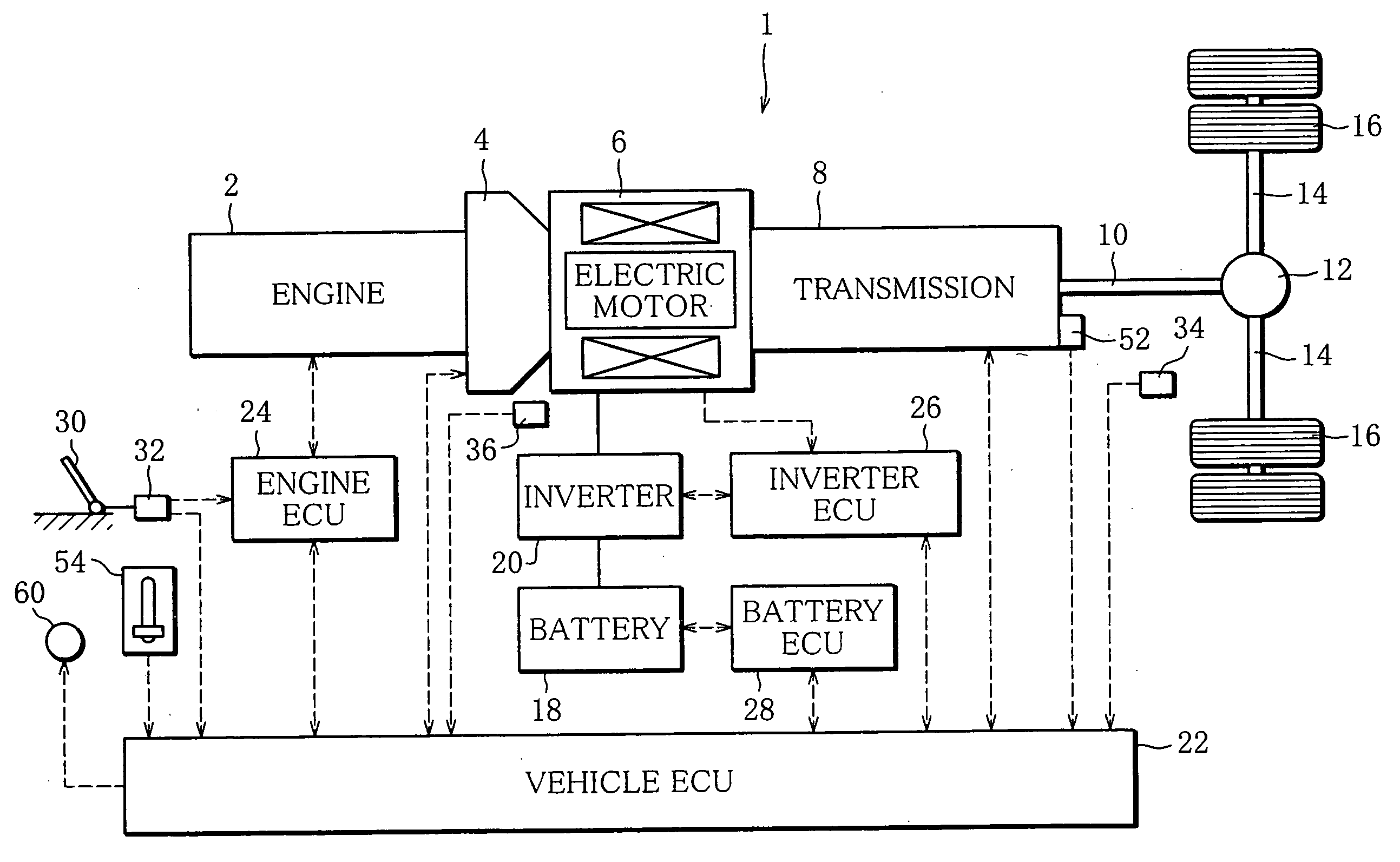
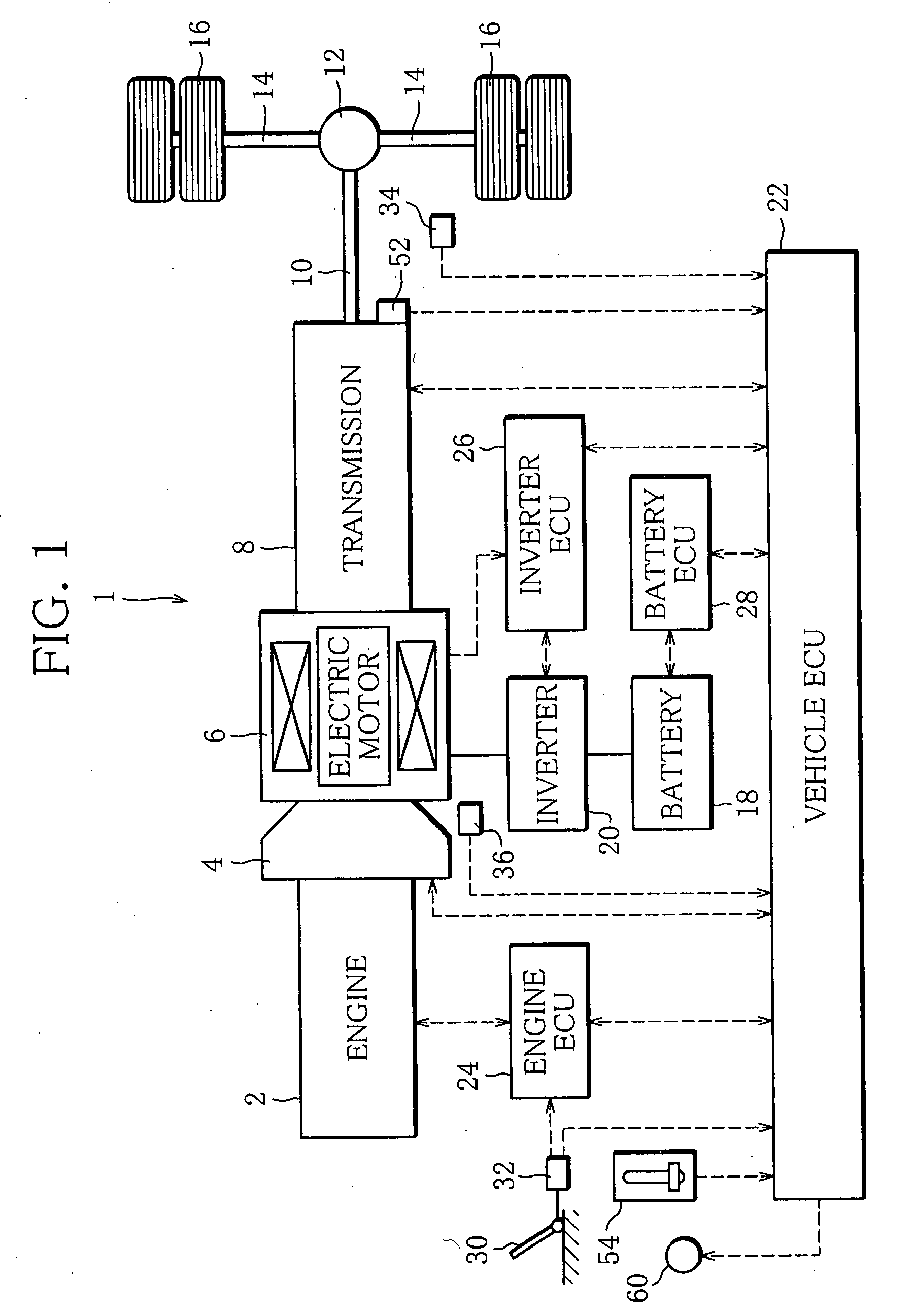
[0020]FIG. 1 is a diagram showing the schematic structure of a hybrid electric vehicle 1 to which the present invention is applied.

[0021]An input shaft of a clutch 4 is coupled with an output shaft of an engine 2, which is a diesel engine. An output shaft of the clutch 4 is coupled to an input shaft of an automatic transmission (hereinafter referred to as “transmission”) 8 through a rotary shaft of a permanent-magnetic synchronous motor (hereinafter referred to as “electric motor”) 6. An output shaft 8 of the transmission 8 is connected to right and left driving wheels 16 through a propeller shaft 10, a differential gear unit 12 and driving shafts 14.

[0022]Thus, when the clutch 4 is engaged, the output shaft of the engine 2 and the rotary shaft of the electric motor 6 are coupled together and can be mechanically connected with the driving wheels 16 through the transmission 8. Mea...


PUM


Abstract

An electric vehicle is provided with an electric motor and a transmission capable of being shifted by a shift mechanism from a neutral state to a start-up speed stage selected state in which a speed stage for start-up of the vehicle has been selected. On a request for a shift from the neutral state to the start-up speed stage selected state, an ECU performs the requested shift by controlling the shift mechanism. If the shift to the start-up speed stage selected state is not completed within a first specified time, the ECU performs a rotating position control in which the motor is controlled to produce a predetermined minute torque in forward and backward rotation directions of the motor, alternately, and a gear of the speed stage for start-up is caused to oscillate in a rotation direction by the minute torque being transmitted to an input shaft of the transmission.

Description

BACKGROUND OF THE INVENTION[0001]1. Field of the Invention[0002]This invention relates to a control device for an electric vehicle, and particularly a control device for an electric vehicle arranged such that a driving force of an electric motor can be transmitted to the driving wheels of the vehicle through a transmission capable of being shifted, by means of a shift mechanism, from neutral state to a state in which a speed stage for start-up of the vehicle has been selected (hereinafter such speed stage is referred to as “vehicle start-up speed stage”).[0003]2. Description of the Related Art[0004]An electric vehicle arranged such that a driving force of an electric motor is transmitted to the driving wheels of the vehicle is known. In recent years, in order to improve practical utility, there has been developed and come into practical use a hybrid electric vehicle in which also an engine is mounted in combination with an electric motor such that a driving force of the engine and a...

Claims


Application Information

Patent Timeline
Patent Type & Authority Applications(United States)
IPC IPC(8): B60K1/02B60W10/04B60K6/48B60K6/547B60L50/16B60W10/08B60W10/10B60W20/00F16H59/10F16H59/70F16H61/04F16H61/68F16H61/682F16H63/50
CPCB60K6/48Y10T477/343B60W10/08B60W10/11B60W20/00B60W30/18027B60W30/19Y02T10/6217Y02T10/6221Y02T10/7077Y10T477/656Y10T477/23Y10T477/26Y10T477/60B60L11/123B60L50/61Y02T10/62Y02T10/70B60W20/30Y02T10/7072
Inventor OGATA, MAKOTO
Owner MITSUBISHI FUSO TRUCK AND BUS CORPORATION
Why Eureka
Try Eureka