Hydraulic metering mode transitioning technique for a velocity based control system

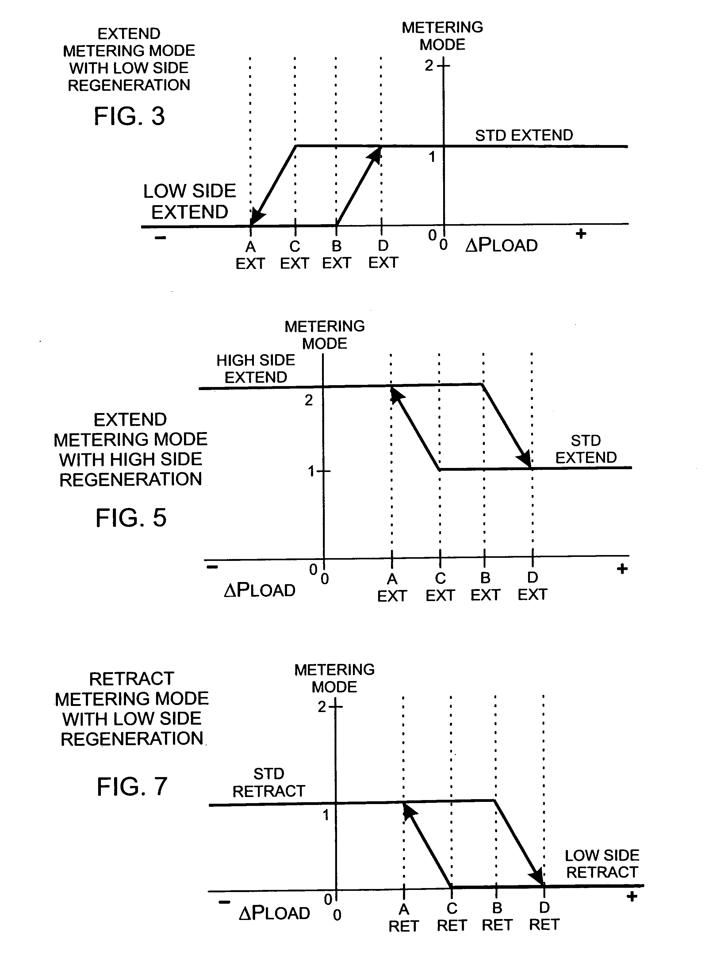
a control system and hydraulic metering technology, applied in the direction of fluid couplings, servomotors, couplings, etc., can solve problems such as hysteresis in the transition function

Inactive Publication Date: 2007-10-04
HUSCO INT INC
View PDF15 Cites 17 Cited by
  • Summary
  • Abstract
  • Description
  • Claims
  • Application Information

AI Technical Summary

Benefits of technology

[0013] The process for selecting which metering mode to use at any point in time involves determining a parameter, referred to herein as the hydraulic load, which denotes an amount of force acting on the actuator. The magnitude of the hydraulic load is used to choose a particular metering mode from the plurality of available modes. The hydraulic system has a first state in which only a standard metering mode is active to control the actuator, and has a second state in which only a regeneration metering mode is active. In a third state, a combination of the standard and regeneration metering modes is utilized, which provides a state that smoothes a transition between the first and second states. While the third state is operational, two metering modes are used in proportion to a proportional relationship of the hydraulic load to the first and second thresholds.

Problems solved by technology

Preferably, the change between the two metering modes occur at different levels of the hydraulic load depending upon the direction of that transition, thereby producing a transition function that has hysteresis.

Method used


Image

  • Hydraulic metering mode transitioning technique for a velocity based control system
  • Hydraulic metering mode transitioning technique for a velocity based control system
  • Hydraulic metering mode transitioning technique for a velocity based control system

Examples


Embodiment Construction

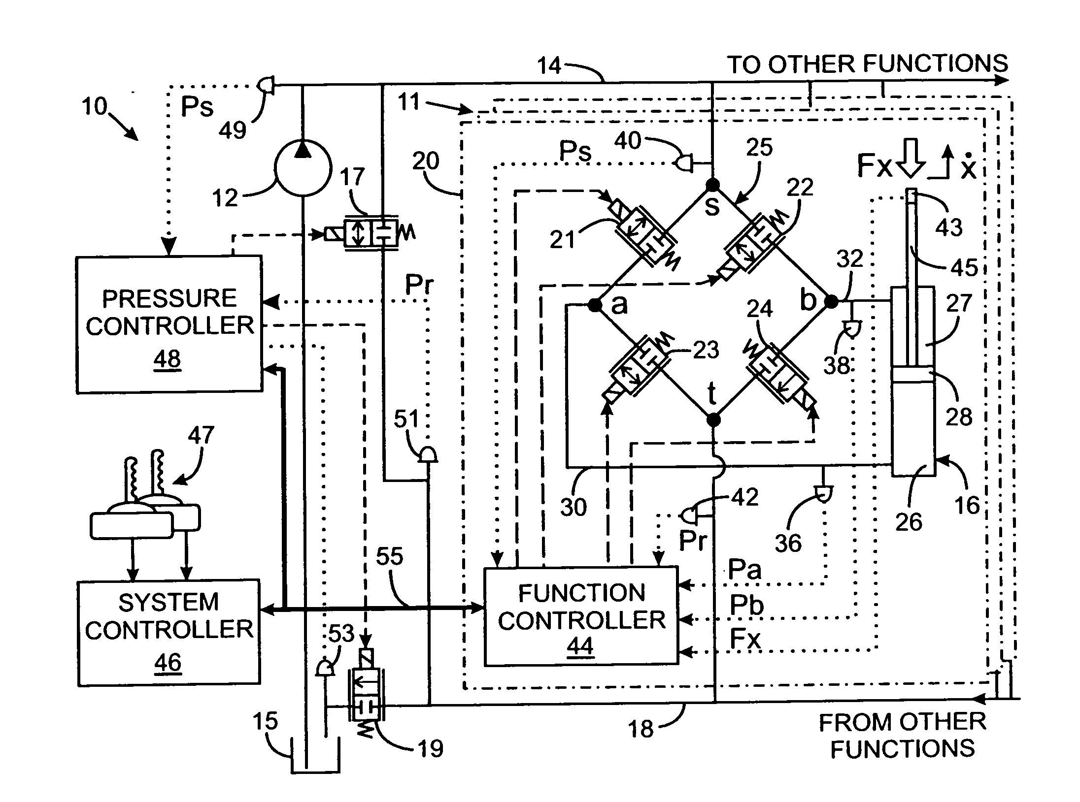
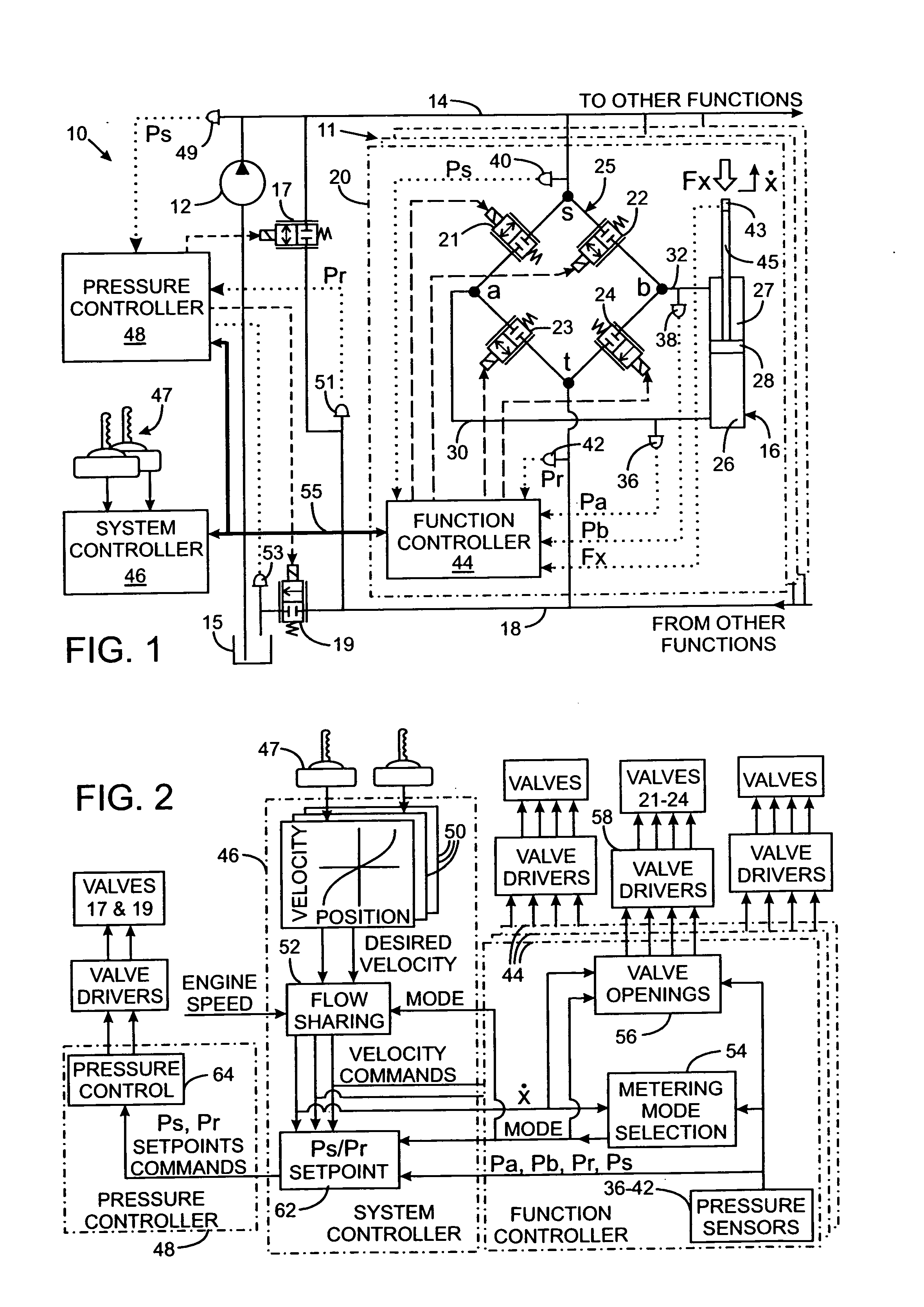
[0023]FIG. 1 shows a hydraulic system 10 for a machine is shown that has mechanical elements operated by hydraulically driven actuators, such as cylinder 16 or rotational motors. The hydraulic system 10 includes a positive displacement pump 12 that is driven by an engine or electric motor (not shown) to draw hydraulic fluid from a tank 15 and furnish the hydraulic fluid under pressure to a supply line 14. The supply line 14 is coupled to a tank return line 18 by a proportional unloader valve 17 and the tank return line 18 is connected by tank control valve 19 to the system tank 15. It should be understood that the novel techniques for apportioning fluid flow described herein also can be implemented on a hydraulic system that employs a variable displacement pump and other types of hydraulic actuators.

[0024] The supply line 14 and the tank return line 18 are connected to a plurality of hydraulic functions on the machine on which the hydraulic system 10 is located. One of those functi...


PUM


Abstract

The flow of fluid to a hydraulic actuator is controlled by a valve assembly which operates in different metering modes at various points in time for energy conservation. The metering mode to use is selected in response to the hydraulic load acting on the hydraulic actuator. Specifically, the present magnitude of hydraulic load is determined and compared to first and second thresholds. Below the first threshold only a first metering mode is activated, and only a second metering mode is activated above the second threshold. A combination of the first and second metering modes is utilized when the hydraulic load is between those thresholds, wherein the metering modes are used in proportion to a proportional relationship of the hydraulic load to the first and second thresholds. Using a metering mode combination in this manner smoothes transitions between the first and second metering modes.

Description

CROSS-REFERENCE TO RELATED APPLICATIONS [0001] Not Applicable. STATEMENT REGARDING FEDERALLY SPONSORED RESEARCH OR DEVELOPMENT [0002] Not Applicable. BACKGROUND OF THE INVENTION [0003] 1. Field of the Invention [0004] The present invention relates to electrically controlled hydraulic systems for operating machinery, and in particular to determining in which one of a plurality of hydraulic fluid metering modes the system should operate at any given time. [0005] 2. Description of the Related Art [0006] A wide variety of machines have members which are moved by a hydraulic actuator, such as a cylinder and piston arrangement, that is controlled by a hydraulic valve. Traditionally the hydraulic valve was manually operated by the machine user. There is a present trend away from manually operated hydraulic valves toward electrical controls and the use of electrohydraulic valves, such as those driven by solenoids. This type of control simplifies the hydraulic plumbing as the control valves ...

Claims


Application Information

Patent Timeline
Patent Type & Authority Applications(United States)
IPC IPC(8): F16D31/02
CPCF15B11/006F15B11/024F15B21/082F15B21/085F15B21/14F15B2211/88F15B2211/6309F15B2211/6313F15B2211/6346F15B2211/7053F15B2211/30575
Inventor PFAFF, JOSEPH L.
Owner HUSCO INT INC
Why Eureka
Try Eureka