Machine provided with pulsating oil pressure reducing device

a technology of pulsating oil and reducing device, which is applied in the direction of machines/engines, auxiliary lubrication, crankcase compression engine lubrication, etc., can solve the problems of oil pan noise generation, oil filter noise generation, vibration and noise generation, etc., to facilitate the construction of a pulsating oil pressure reducing device, facilitate the effect of discharging air efficiently, and increase the degree of freedom of oil passag

Inactive Publication Date: 2007-10-04
HONDA MOTOR CO LTD
View PDF1 Cites 9 Cited by
  • Summary
  • Abstract
  • Description
  • Claims
  • Application Information

AI Technical Summary

Benefits of technology

[0008]The present invention has been made in view of such a problem and it is therefore an object of the present invention to provide a machine with a pulsating oil pressure reducing device including an oil chamber provided with an air vent port in addition to a connecting port and capable of discharging air efficiently from an oil chamber into an oil passage and of increasing the degree of freedom of placing the oil passage and the oil chamber. Another object of the present invention is to facilitate building a pulsating oil pressure reducing device, to improve the adaptability of a pulsating oil pressure reducing device to the variable placement of a machine, and to reduce the cost of a pulsating oil pressure reducing device.
[0010]According to the present invention, the air vent passage opens into the oil passage at a position at a level above the inlet port opening into a top part of the oil chamber in which air is likely to accumulate. Therefore, air accumulated in the oil chamber can be efficiently discharged into the oil passage and hence pulsating oil pressure can be effectively reduced. The oil chamber of the pulsating oil pressure reducing device is provided with the connecting port and the air vent passage separately from the connecting port. Therefore, the placement of the oil chamber is not restricted by the position of the connecting port. Since the air vent passage needs to meet only a condition requiring opening the outlet port of the air vent passage into the oil passage at a position at a level above the inlet port of the air vent passage, the oil passage and the oil chamber do not need necessarily to be vertically arranged, and air can be efficiently discharged from the oil chamber into the oil passage even if the oil passage and the oil chamber are horizontally arranged. Thus the pulsating oil pressure reducing device provides a large degree of freedom of placing the oil passage and the oil chamber.
[0012]Thus air accumulated in the oil chamber can be efficiently discharged into the oil passage and hence the pulsating oil pressure can be effectively reduced even if the construction of the machine requires the horizontal side-by side arrangement of the oil passage and the oil chamber.
[0014]When the horizontally elongate oil passage and the horizontally elongate oil chamber are disposed vertically close to each other, air accumulated in the oil chamber, in which air can more easily accumulate than in a vertically elongate oil chamber, can be efficiently discharged through the air vent passage and pulsating oil pressure can be effectively reduced.
[0016]Since the upper side surface of the air vent passage slopes upward from the oil chamber toward the oil passage, air accumulated in the oil chamber can easily flow toward the oil passage and hence air can be efficiently discharged from the oil chamber.
[0018]When the oil passage is defined by both the upper and the lower member, and the oil chamber is formed only in the lower member, the air vent passage having its inlet port formed in the top ceiling surface of the oil chamber and the outlet port opening into the oil passage can be easily formed. Since the connecting port is formed in the lower member, air discharged through the air vent passage cannot easily return through the connecting port into the oil chamber. Since the air vent passage is formed in the upper member, change in the inclination of the machine to a horizontal plane and resulting change in the position of a space in which air accumulates can be dealt with without changing the lower member and by replacing the upper member with another upper member provided with an air vent passage suitable for the inclination of machine. Thus the pulsating oil pressure reducing device has high applicability to various positions of the machine and can reduce the cost of the internal combustion engine.

Problems solved by technology

The pulsating oil pressure causes undesirable phenomena including vibration and noise generation.
For example, the pulsating oil pressure vibrates an oil filter placed in the discharge passage and causes the oil filter to generate noise.
The pulsating oil pressure in the suction passage propagated to the oil contained in an oil pan vibrates the oil pan and causes the oil pan to generate noise.
Air leaks through small gaps into oil passages and the oil pump while the oil pump is not operating.
If an oil passage and an oil chamber are arranged horizontally in side-by-side relation, it is difficult to discharge air efficiently through a discharge port formed in the upper part of the oil chamber into the oil passage.

Method used


Image

  • Machine provided with pulsating oil pressure reducing device
  • Machine provided with pulsating oil pressure reducing device
  • Machine provided with pulsating oil pressure reducing device

Examples


Embodiment Construction

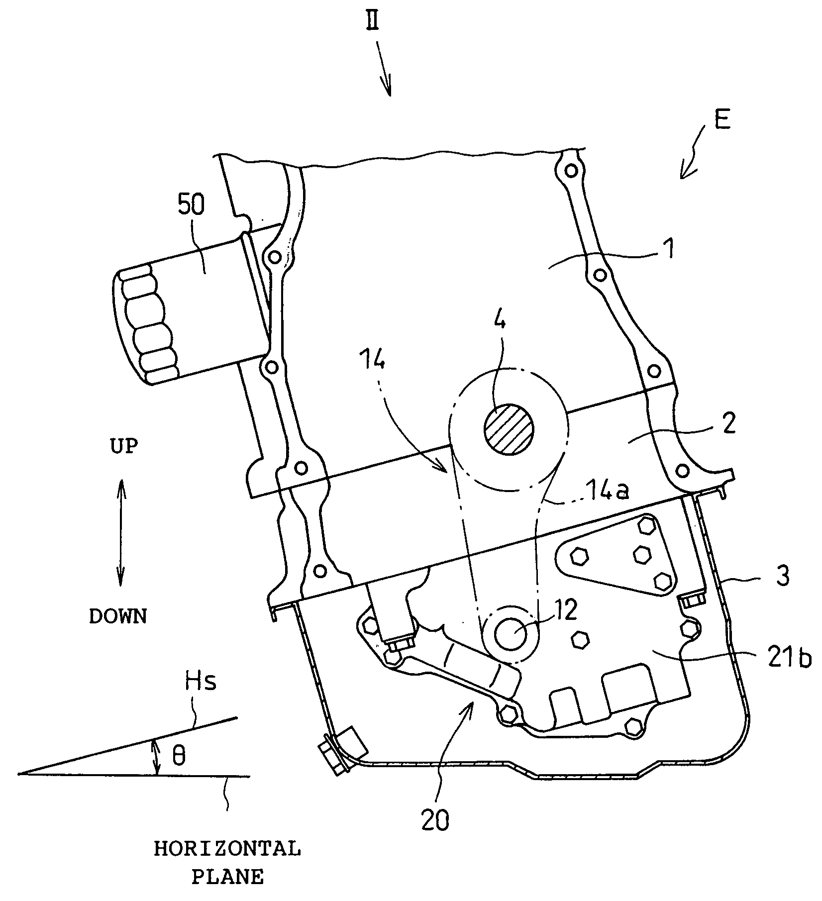
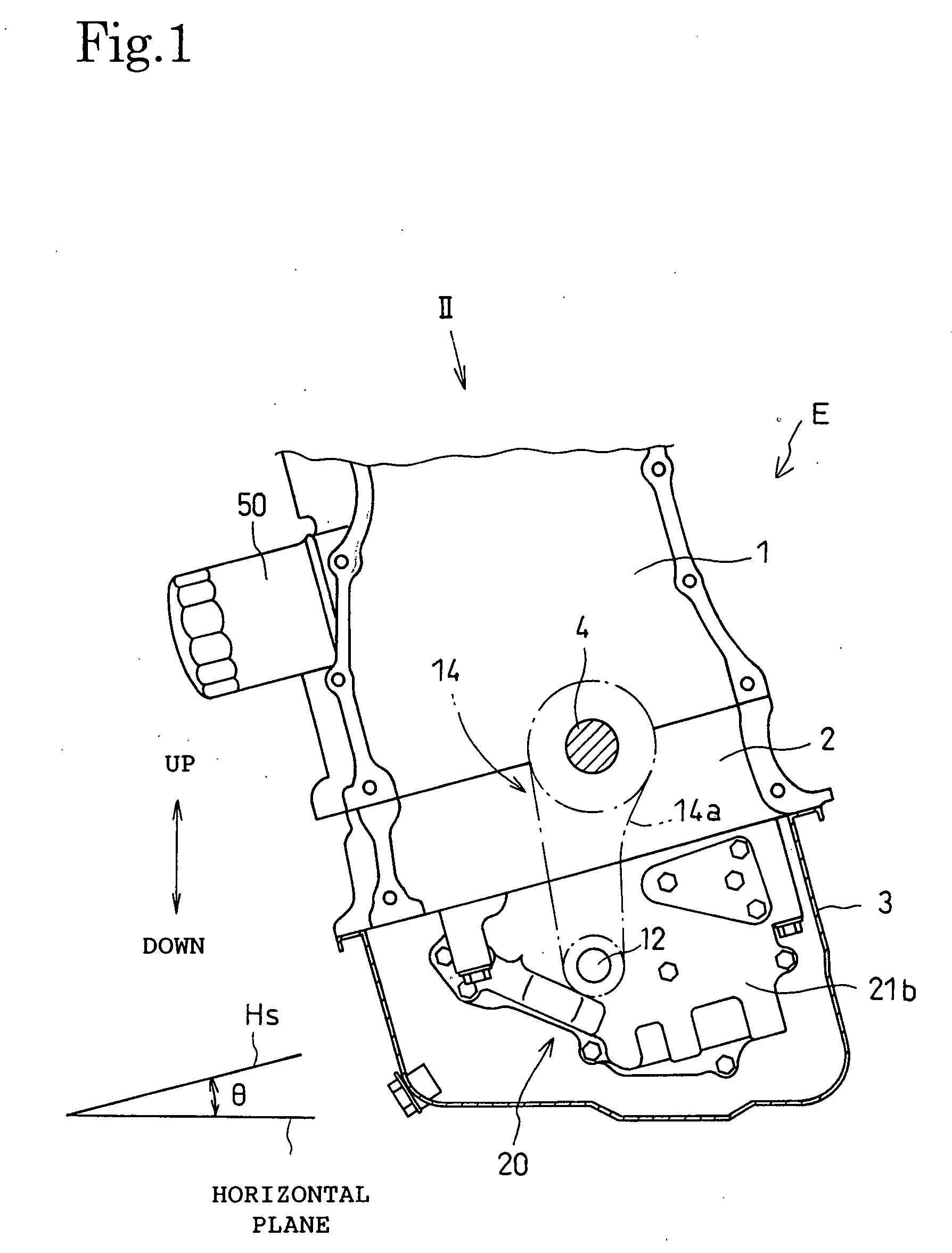
[0033]An internal combustion engine E in a preferred embodiment of the present invention will be described with reference to the accompanying drawings.

[0034]Referring to FIG. 1, the internal combustion engine E is an in-line 4-cylinder 4-stroke internal combustion engine mounted on a transverse-engine vehicle with its crankshaft 4 extending transversely. The internal combustion engine E has an engine body including a cylinder block 1 provided with four cylinders and four pistons axially slidably fitted in the cylinders, respectively, for reciprocation, a lower block 2 joined to the lower end surface of the cylinder block 1, and an oil pan 3 joined to the lower end surface of the lower block 2. Pistons driven by the pressure of a combustion gas produced by the combustion of an air-fuel mixture in combustion chambers drive the crankshaft 4 rotatably supported on the cylinder block 1 and the lower block 2 for rotation. The engine body is mounted on the body of the vehicle with a plane ...


PUM


Abstract

A pulsating oil pressure reducing device 40 for an internal combustion engine has an oil chamber 41 for reducing pulsating oil pressure in a discharge passage 30 for carrying oil discharged from an oil pump 20. The oil chamber 41 communicates with the discharge passage 30 by way of a connecting port 41a1 and makes the oil stagnate therein. The oil chamber 41 is connected to the discharge passage 30 by an air vent passage 45 through which air is discharged from the oil chamber 41 into the discharge passage 30. The air vent passage 45 has an inlet port 45a opening into a top part 41a of the oil chamber 41 and a discharge port 45b opening into the oil passage 30 at a level above the inlet port 45a. Since the pulsating oil pressure reducing device 40 having the air vent passage separately from the connecting port, air can be efficiently discharged from the oil chamber and the degree of freedom of placement of the oil passage and the oil chamber is increased.

Description

BACKGROUND OF THE INVENTION[0001]1. Technical Field[0002]The present invention relates to a machine provided with a pulsating oil pressure reducing device for reducing the pulsating oil pressure in an oil passage, such as an internal combustion engine provided with an oil pump.[0003]2. Description of the Related Art[0004]In a positive-displacement oil pump, the volume of an enclose space is increased to suck an oil into the enclosed space and is decreased to discharge the oil from the enclosed space. Therefore, both oil pressure in the suction passage connected to the inlet port of the positive-displacement oil pump and oil pressure in the discharge passage connected to the outlet port of the positive-displacement oil pump pulsate. The pulsating oil pressure causes undesirable phenomena including vibration and noise generation. For example, the pulsating oil pressure vibrates an oil filter placed in the discharge passage and causes the oil filter to generate noise. The pulsating oil...

Claims


Application Information

Patent Timeline
Patent Type & Authority Applications(United States)
IPC IPC(8): F01M13/00F01M3/04F02B25/06F01M1/02
CPCF01M11/02F01M1/16
Inventor TSURUTA, TATSUNORIKAWAI, NORIAKINISHIKAWA, CHIHIROTAKAHASHI, NOBUHARU
Owner HONDA MOTOR CO LTD
Why Eureka
Try Eureka