Microfluidic devices for the controlled manipulation of small volumes

a microfluidic device and fluidic technology, applied in flow mixers, electrocardialysis, digital storage, etc., can solve the problems of insufficient development, unfavorable general implementation, and unknown devices that have not exploited new experimental approaches

a microfluidic device and fluidic technology, applied in flow mixers, electrocardialysis, digital storage, etc., can solve the problems of insufficient development, unfavorable general implementation, and unknown devices that have not exploited new experimental approaches

US20070227890A1Inactive Publication Date: 2007-10-04UT BATTELLE LLC

Image

  • Microfluidic devices for the controlled manipulation of small volumes
  • Microfluidic devices for the controlled manipulation of small volumes
  • Microfluidic devices for the controlled manipulation of small volumes

Examples


Embodiment Construction

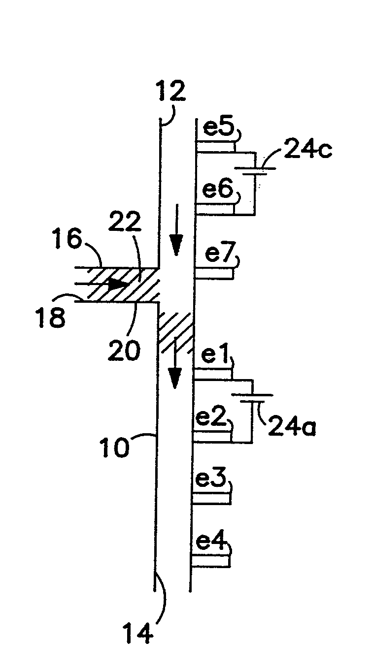
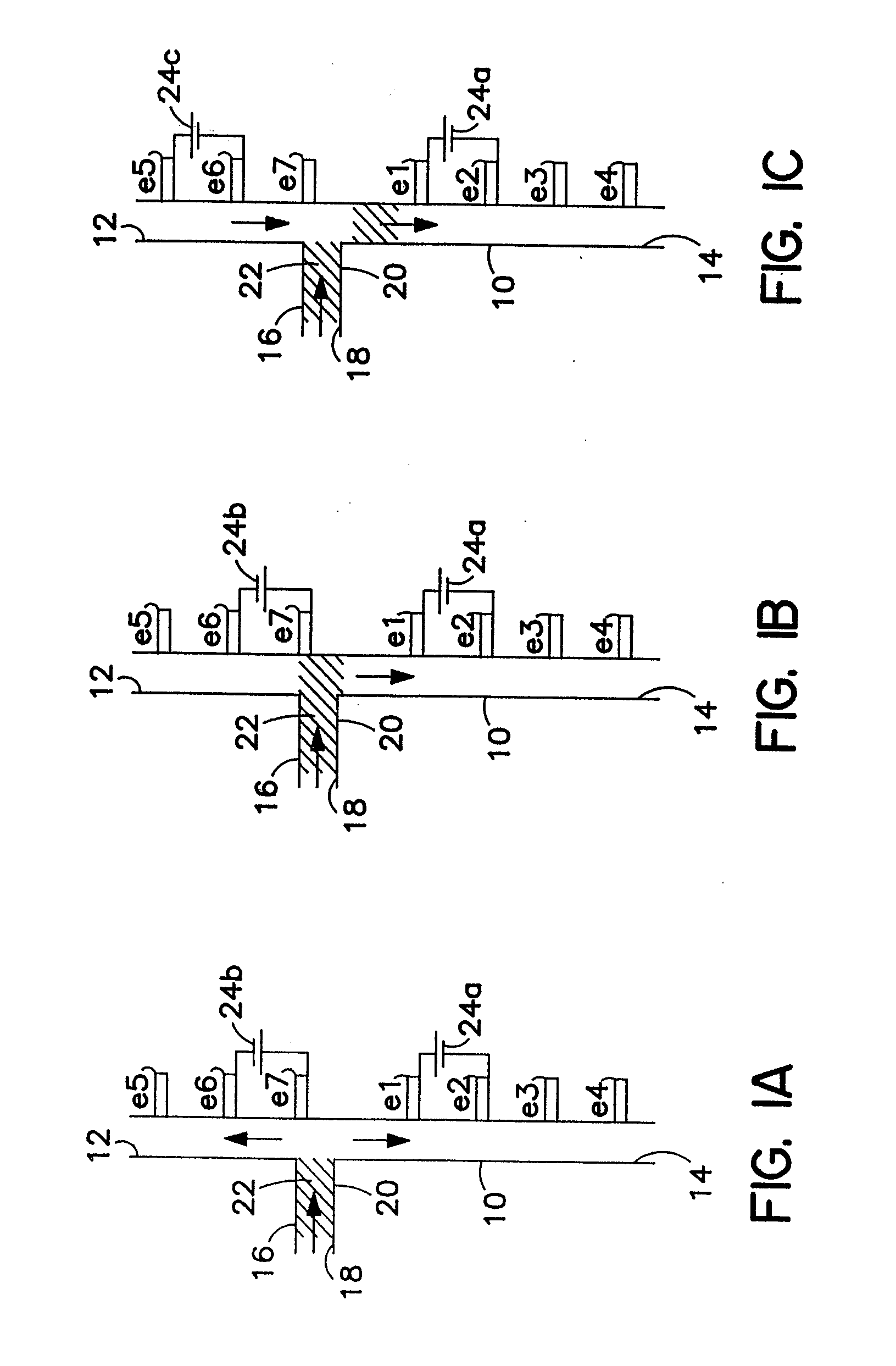
[0024] Referring now to the drawings, wherein like reference numerals refer to the same or similar components or features, and in particular to FIGS. 1A, 1B, and 1C, there is shown a main microchannel 10. Main microchannel 10 is substantially linear and has an inlet 12 that is connected to a source of transport fluid (not shown) and an outlet 14 that is connected to a waste reservoir (not shown). A branch channel 16 has an inlet 18 and an outlet 20 that intersects with the main microchannel 10 for conducting a segmenting or isolating fluid 22 into the main channel 10. Electrodes e1, e2, e3, and e4 are disposed at spaced apart locations along main microchannel 10 between outlet 20 and outlet 14. Electrodes e5, e6, and e7 are disposed at spaced apart location along the side of main microchannel between outlet 20 an inlet 12. All electrodes are in contact with fluids contained within the microchannels. Either the transport fluid, the segmenting fluid, or both are transportable through ...


PUM

PropertyMeasurementUnit
diameteraaaaaaaaaa
volumesaaaaaaaaaa
volumeaaaaaaaaaa

Abstract

A method for conducting a broad range of biochemical analyses or manipulations on a series of nano- to subnanoliter reaction volumes and an apparatus for carrying out the same are disclosed. The invention is implemented on a fluidic microchip to provide high serial throughput. In particular, the disclosed device is a microfabricated channel device that can manipulate nanoliter or subnanoliter reaction volumes in a controlled manner to produce results at rates of 1 to 10 Hz per channel. The reaction volumes are manipulated in serial fashion analogous to a digital shift register. The invention has application to such problems as screening molecular or cellular targets using single beads from split-synthesis combinatorial libraries, screening single cells for RNA or protein expression, genetic diagnostic screening at the single cell level, or performing single cell signal transduction studies.

Description

CROSS-REFERENCE TO RELATED APPLICATIONS [0001] This application is a continuation of application Ser. No. 09 / 408,060, filed Sep. 29, 1999, which in turn claims the benefit of priority of U.S. Provisional Application 60 / 148,502, filed on Aug. 12, 1999, the contents of which are incorporated herein by reference.[0002] The United States Government has rights in this invention pursuant to contract no. DE-AC05-00OR22725 between the United States Department of Energy and UT-Battelle, LLC.FIELD OF THE INVENTION [0003] This invention relates to a microfabricated fluidic device, and in particular, to such a device that is configured for forming and transporting a series of minute volume segments of a material and for storage, retrieval, and analysis thereof and to a method for forming, transporting, storing, and retrieving such a series of minute volume segments. BACKGROUND OF THE INVENTION [0004] A number of elementary microfabricated fluidic devices have been demonstrated over the past few...

Claims


Application Information

Patent Timeline
04 Oct 2007
Publication
US20070227890A1
IPC
G01N27/447; B01D57/02; B01F5/04; B01F13/00; B01J4/00; B01J19/00; B01J19/32; B01L3/00; B03C5/00; F15C5/00; F16K99/00; G01N35/08; G01N37/00; G11C19/00; G11C25/00
CPC
B01F5/0471; Y10T436/2575; B01F13/0076; B01F13/0077; B01J19/0093; B01J2219/00853; B01J2219/00891; B01L3/502761
Inventors
RAMSEY, J. MICHAEL; JACOBSON, STEPHEN C.