Wireless audio signal receiver device for a hearing instrument

a receiver device and audio signal technology, applied in the direction of flexible aerials, antennas, collapsible antennas, etc., can solve the problems of large geometrical dimensions, instruction of users, and large dimensions of receiver devices, so as to reduce the volume of the receiver device, avoid rotatable connectors, and be more compact

Active Publication Date: 2007-10-04
SONOVA AG
View PDF3 Cites 82 Cited by
  • Summary
  • Abstract
  • Description
  • Claims
  • Application Information

AI Technical Summary

Benefits of technology

[0016] The solution according to claims 1 and 4 is beneficial in that, by using a magnetic loop antenna which comprises a first portion defining a first plane and a second portion defining a second plane, wherein the first plane and the second plane are oriented at an angle of 60 to 120°, it is ensured that at least one portion of the antenna is always oriented at least close to the optimum direction, whatever the actual orientation of the receiver device—depending on the type of hearing instrument to which it is to be connected—on the user's head will be. In addition, in view of the fact that usually the housing of such receiver device will have walls which are oriented relative to each other at an angle of typically between 60 and 120° the geometry of the magnetic loop antenna can be adapted to the geometry of the housing, whereby the volume of the receiver device can be reduced. In particular, also the need for a rotatable connector is avoided. Consequently, a more simple, smaller, more compact and also more robust receiver device can be achieved.
[0017] The solution according to claims 11 and 12 is beneficial in that, by providing a magnetic loop antenna which comprises a first portion defining a first plane and a second portion defining a second plane, wherein the first plane and the second plane are oriented at an angle of 60 to 120°, a relatively small, compact and robust hearing instrument can be achieved.
[0027] The solution according to claim 13 is beneficial in that, by orienting the antenna plane or antenna direction, respectively, at an angle of 30 to 60 degrees, preferably at 40 to 50 degrees, with respect to the central symmetry plane of the output interface, it is ensured due to the fact that the orientation of the input interface or the adapter interface (audio shoe) typically differs by ±90 degrees or ±180 degrees from type to type of the hearing instrument so that also the relative orientation of the receiver device when connected to the hearing instrument would differ by 90 degrees or 180 degrees depending on the type of hearing instrument—that the orientation of the antenna to the user's head anatomy, in particular to the direction of the user's nose, differs by significantly less than 90 degrees depending on the type of hearing instrument so that the worst case in which the antenna is oriented more or less parallel to the direction of the user's nose can be avoided.
[0029] The solution according to claim 22 is beneficial in that, by forming a printed board circuit antenna and at least a portion of the signal processing unit as an integral electronic unit on a common printed circuit board comprising an at least partially flexible insolating substrate which is capable of being partially folded for mounting the printed circuit board into the housing, manufacturing of the receiver device is made particularly simple, since the antenna and at least a portion of the signal processing unit can be processed as an integral electronic unit, while, due to the foldability of the substrate, nevertheless a compact design can be achieved.

Problems solved by technology

However, the orientation of the three pins in the audio shoe with respect to the hearing instrument, i.e. with respect to the user's head, is not standardized and therefore varies from type to type.
A drawback of this solution is that a rotatable connector results in larger dimensions of the receiver device, given by the space required to design and implement a reliable and stable mechanical solution for the connector rotation.
In addition, the electrical connections between the connector and the electronic module of the receiver device need to be flexible in order to allow the rotation of the connector with respect to the electronic module, which results in additional complexity, e.g. soldered wires, and again larger geometrical dimensions.
A further drawback is the need to instruct the user regarding how to manipulate the receiver device, i.e. how to rotate the connector, on all sorts and types of combinations of hearing instruments and audio shoes.

Method used


Image

  • Wireless audio signal receiver device for a hearing instrument
  • Wireless audio signal receiver device for a hearing instrument
  • Wireless audio signal receiver device for a hearing instrument

Examples


Embodiment Construction

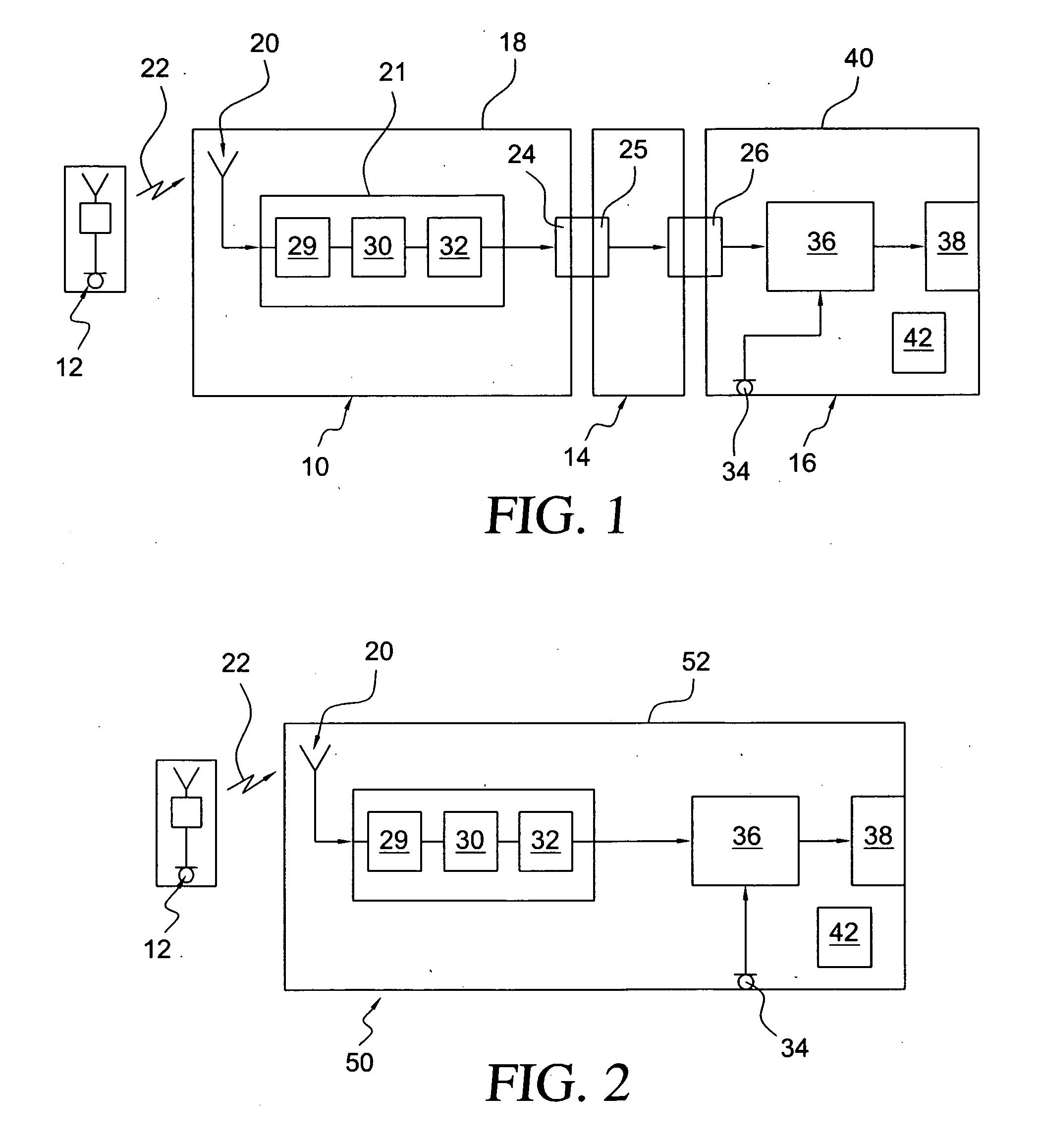
[0040]FIG. 1 shows a block diagram of a receiver device 10 capable of wirelessly receiving audio signals from a remote source 12, which is connected via an audio shoe 14 to a healing instrument 16 which may be a behind-the-ear (BTE) hearing aid which is worn at the user's ear. The remote audio signal source typically may be a transmitter unit comprising a microphone which is worn by a teacher in a classroom for teaching hearing-impaired pupils.

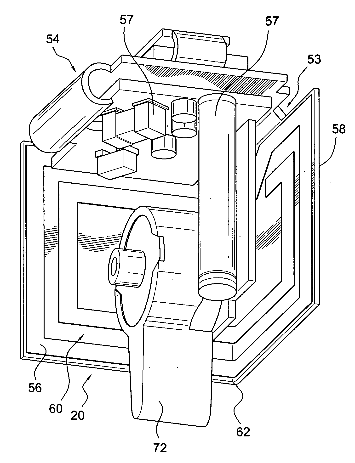
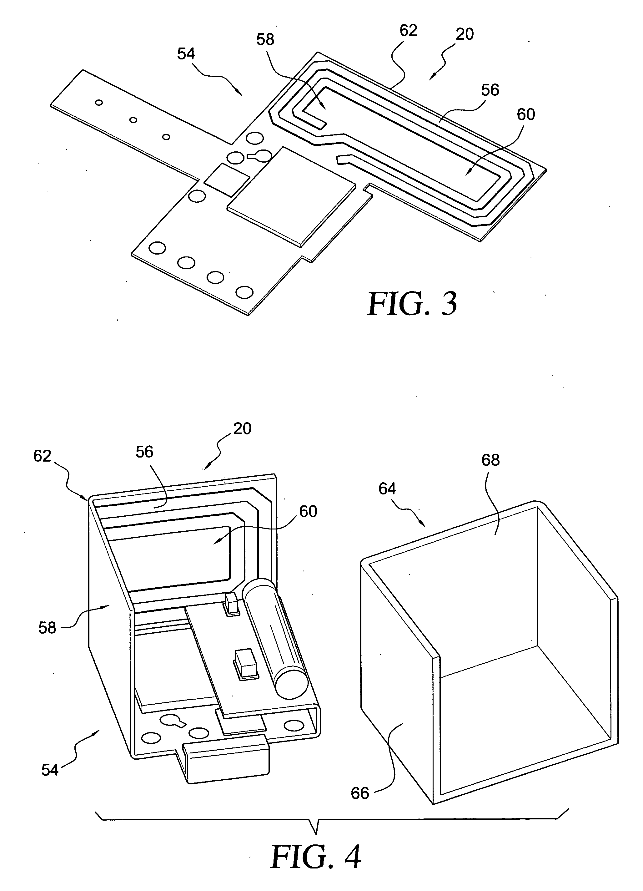
[0041] The receiver device 10 comprises a housing 18, a magnetic loop-antenna 20 for receiving radio-frequency signals carrying audio-signals from the remote source 12 via a radio-frequency link 22, a signal processing unit 21 for reproducing audio signals from the radio frequency signals received by the antenna 20, and an output interface 24 which is capable of being mechanically connected to an input interface 26 of the hearing instrument 16 via the audio shoe 14 which comprises an input interface 25 mating with the output interface 24. The...


PUM

PropertyMeasurementUnit
angleaaaaaaaaaa
angleaaaaaaaaaa
angleaaaaaaaaaa

Abstract

A receiver device (10) for receiving audio signals from a remote source is provided, comprising: a magnetic loop antenna for receiving radio frequency signals carrying audio signals, a signal processing unit for reproducing audio signals from the radio frequency signals received by the antenna, an output interface which is capable of being mechanically connected to an input interface of a hearing instrument to be worn at a user's ear in order to supply the audio signals from the signal processing unit as input to the hearing instrument, and a housing enclosing the antenna and the signal processing unit, wherein the antenna is designed as a printed board circuit with a loop-like conductor on an at least partially flexible insolating substrate and comprises a first portion defining a first plane and a second portion defining a second plane, wherein the first plane and the second plane are oriented at an angle of 60 to 120 degrees relative to each other.

Description

BACKGROUND OF THE INVENTION [0001] 1. Field of the Invention [0002] The present invention relates to a wireless receiver device for wirelessly receiving audio signals from a remote source, which is capable of supplying such audio signal to a hearing instrument. The invention also relates to a hearing instrument which is capable of wirelessly receiving audio signals from a remote source. [0003] 2. Description of Related Art [0004] It is well-known to use a receiver device (usually an FM (frequency modulation) receiver) for receiving audio signals from a remote source, for example a remote microphone, via a wireless link (usually an FM link) in order to provide such audio signals as input signals to a hearing instrument worn at a user's ear. To this end the receiver device has an output interface which is capable of being mechanically connected to an input interface of the hearing instrument via a so-called “audio shoe”. The audio shoe is mechanically connected to the input interface ...

Claims


Application Information

Patent Timeline
Patent Type & Authority Applications(United States)
IPC IPC(8): H01Q1/24H01Q1/12
CPCH01Q1/085H01Q1/273H01Q7/00Y10T29/49572H04R25/554H04R25/556H04R2225/51H01Q7/08
Inventor PLATZ, RAINER
Owner SONOVA AG
Why Eureka
Try Eureka