Channel equalizer and method of processing broadcast signal in DTV receiving system

a channel equalizer and broadcast signal technology, applied in the field of digital telecommunications systems, can solve the problems of data transmission that is to be transmitted, data quality that is to be deteriorated, and the intensity of signals may decrease, so as to compensate channel distortion

Inactive Publication Date: 2007-10-04
LG ELECTRONICS INC
View PDF99 Cites 63 Cited by
  • Summary
  • Abstract
  • Description
  • Claims
  • Application Information

AI Technical Summary

Benefits of technology

[0010] A further object of the present invention is to provide a channel equalizer and a method of processing broadcast signal in DTV receiving system that can use pre-defined known data that are already known by a receiving system and / or a transmitting system, thereby enhancing the receiving performance of the digital broadcast (or television) receiving system.
[0012] To achieve these objects and other advantages and in accordance with the purpose of the invention, as embodied and broadly described herein, a channel equalizer for use in a digital television (DTV) receiving system includes a first transformer, an estimator, an average calculator, a second transformer, a coefficient calculator, a compensator, and a third transformer. The first transformer converts normal data in a broadcast signal into frequency domain data. A known data sequence is periodically repeated in the normal data. The estimator estimates channel impulse responses during intervals in which first and second known data sequences located before and after each normal data block in the broadcast signal are received. The average calculator calculates an average value of the estimated channel impulses, and the second transformer converts the average value into frequency domain data. The coefficient calculator calculates equalization coefficients using the average value in the frequency domain. The compensator compensates channel distortion of each normal data block in the frequency domain by multiplying each normal data block with the equalization coefficients. Finally, the third transformer converts the compensated normal data block into time domain data.
[0013] In another aspect of the present invention, a channel equalization for use in a digital television (DTV) receiving system includes an overlap unit, a first transformer, an estimator, a second transformer, a calculator, a compensator, a third transformer, and a save unit. The overlap unit overlaps normal data in a broadcast signal at a predetermined overlap ratio. A known data sequence is periodically repeated in the normal data. The first transformer converts the overlapped normal data into frequency domain data. The estimator estimates a channel impulse response using the known data sequence, and the second transformer converts the estimated channel impulse response into frequency domain data. The calculator calculates equalization coefficients using the estimated channel impulse response in the frequency domain. The compensator compensates channel distortion of the normal data in the frequency domain by multiplying the normal data with the equalization coefficients. The third transformer converts the compensated normal data into time domain data, and the save unit saves the compensated normal data in the time domain.
[0014] In another aspect of the present invention, a channel equalizer for use in a DTV receiving system includes an overlap unit, a first transformer, an estimator, an interpolator, a second transformer, a calculator, a compensator, a third transformer, and a save unit. The overlap unit overlaps normal data in a broadcast signal at a predetermined overlap ratio. A known data sequence is periodically repeated in the normal data. The first transformer converts the overlapped normal data into frequency domain data. The estimator estimates a first channel impulse response during a known data interval, and the interpolator estimates a second channel impulse response during a normal data interval by interpolating the first channel impulse response. The second transformer converts the estimated second channel impulse response into frequency domain data. The calculator calculates equalization coefficients using the second channel impulse response in the frequency domain. The compensator compensates channel distortion of the normal data in the frequency domain by multiplying the normal data with the equalization coefficients. The third transformer converts the compensated normal data into time domain data. Finally, the save unit saves the compensated formal data in the time domain.

Problems solved by technology

However, when used indoors, the intensity of the signals may decrease due to a blockage caused by the walls or disturbance caused by approaching or proximate mobile objects.
Accordingly, the quality of the received digital signals may be deteriorated due to a ghost effect and noise caused by reflected waves.
However, unlike the general video / audio data, when transmitting the supplemental data, the data that is to be transmitted should have a low error ratio.
Conversely, in case of the supplemental data (e.g., program execution file, stock information, etc.), an error even in a single bit may cause a serious problem.
Furthermore, in a poor channel environment, the receiving performance of the conventional receiving system may be deteriorated.

Method used


Image

  • Channel equalizer and method of processing broadcast signal in DTV receiving system
  • Channel equalizer and method of processing broadcast signal in DTV receiving system
  • Channel equalizer and method of processing broadcast signal in DTV receiving system

Examples


first embodiment

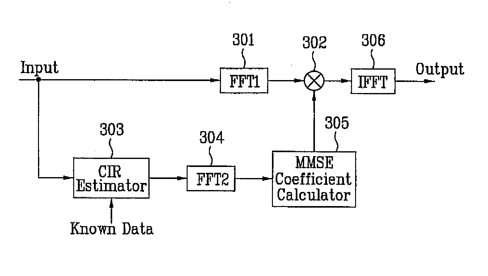
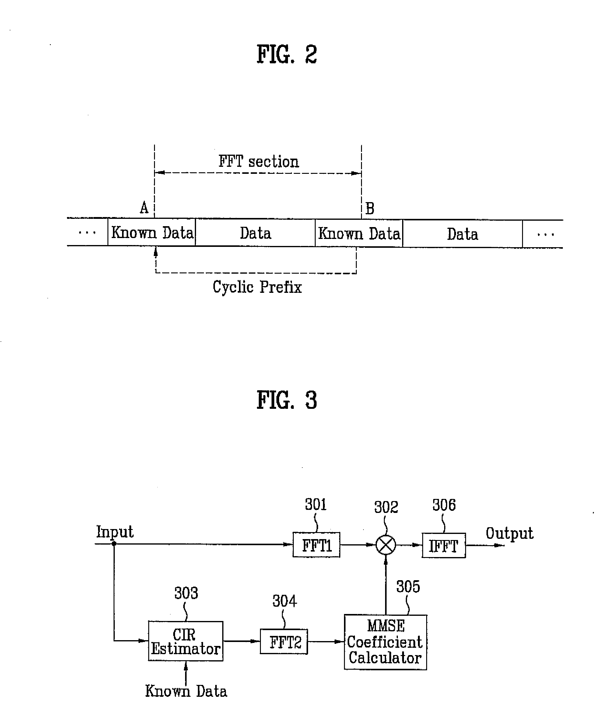
[0041]FIG. 3 illustrates a block diagram of a channel equalizer according to the present invention. More specifically, FIG. 3 illustrates a block diagram of a frequency domain channel equalizer using an indirect equalization method according to the present invention. Referring to FIG. 3, the channel equalizer includes a first fast fourier transform (FFT) unit FFT1301, a distortion compensator 302, a channel estimator 303, a second FFT unit FFT2304, a MMSE coefficient calculator 305, and an inverse fast fourier transform (IFFT) unit 306. Herein, any device performing complex number multiplication may be used as the distortion compensator 302.

[0042] In the channel equalizer having the above-described structure, as shown in FIG. 3, the first FFT unit 301 performs a FFT process on the received data so as to convert the data to frequency domain data. The frequency domain data are then outputted to the distortion compensator 302. At this point, if known data sequences having the same patt...

second embodiment

[0046] In order to resolve such problems, another example of a channel equalizer is presented in FIG. 4. FIG. 4 illustrates a block diagram of a channel equalizer of the frequency domain according to the present invention. Herein, an average value of the CIRs is used for channel equalizing the general data. More specifically, when performing the equalization process, an average value of the CIR of point A and the CIR of point B is used to perform a channel equalization process on the general data section between point A and point B, thereby enhancing the equalization performance. Accordingly, the channel equalizer shown in FIG. 4 further includes an average calculator 307 between the channel estimator 303 and the second FFT unit 304 of FIG. 3.

[0047] More specifically, the channel estimator 303 estimates the CIR by using the data received during the known data section and the known data. Then, the estimated CIR is outputted to the average calculator 307. Herein, the average calculato...

fifth embodiment

[0062]FIG. 10 illustrates a block diagram of a channel equalizer according to the present invention. More specifically, FIG. 10 illustrates a block diagram showing the structure of a channel equalizer of a frequency domain using a direct equalization method according to the present invention. Referring to FIG. 10, the channel equalizer includes an overlap unit 501, a first fast fourier transform (FFT) unit 502, a distortion compensator 503, an inverse fast fourier transform (IFFT) unit 504, a save unit 505, a decision unit 506, a select unit 507, a subtractor 508, a zero padding unit 509, a second FFT unit 510, a coefficient update unit 511, and a delay unit 512. Herein, any device that performs complex number multiplication may be used as the distortion compensator 503.

[0063] In the channel equalizer having the above-described structure, as shown in FIG. 10, the received data are overlapped by the overlap unit 501 and are outputted to the first FFT unit 502. The first FFT unit 502 ...


PUM


Abstract

A channel equalizer includes a first transformer, an estimator, an average calculator, a second transformer, a coefficient calculator, a compensator, and a third transformer. The first transformer converts normal data into frequency domain data, where a known data sequence is periodically repeated in the normal data. The estimator estimates channel impulse responses (CIR) during known data intervals adjacent to each normal data block. The average calculator calculates an average value of the CIRs. The second transformer converts the average value into frequency domain data. The coefficient calculator calculates equalization coefficients using the average value, and the compensator compensates channel distortion of each normal data block using the coefficients. The third transformer converts the compensated data block into time domain data.

Description

[0001] This application claims the benefit of the Korean Patent Application No. 10-2006-0013128, filed on Feb. 10, 2006, which is hereby incorporated by reference as if fully set forth herein. Also, this application claims the benefit of the Korean Patent Application No. 10-2006-0089736, filed on Sep. 15, 2006, which is hereby incorporated by reference as if fully set forth herein. This application also claims the benefit of U.S. Provisional Application No. 60 / 883,154, filed on Jan. 2, 2007, which is hereby incorporated by reference.BACKGROUND OF THE INVENTION [0002] 1. Field of the Invention [0003] The present invention relates to a digital telecommunications system, and more particularly, to a channel equalizer and a method of processing broadcast signal in DTV receiving system. [0004] 2. Discussion of the Related Art [0005] Presently, the technology for processing digital signals is being developed at a vast rate, and, as a larger number of the population uses the Internet, digit...

Claims


Application Information

Patent Timeline
Patent Type & Authority Applications(United States)
IPC IPC(8): H04N11/04
CPCH04L25/0212H04L25/0232H04N19/00933H04N19/89H04N19/895H04L25/03159H04N21/23614H04N21/631H04N5/38H03M13/2936H04N7/12H03M13/6538H04N5/40H04N5/455H04N5/21H04N21/236H03M13/2792H03M13/2906H04L1/0041H04L12/189
Inventor KIM, BYOUNG GILLCHOI, IN HWANKANG, KYUNG WONKWAK, KOOK YEONKIM, WOO CHAN
Owner LG ELECTRONICS INC
Why Eureka
Try Eureka