Method for testing DSL capability of telephone lines

a telephone line and dsl technology, applied in the direction of substation equipment, electrical equipment, supervision/monitoring/testing arrangements, etc., can solve the problems of erroneous test, line test system inability to accurately determine, and limited information provided by lts tests regarding the transfer characteristic of the loop or telephone lin

Active Publication Date: 2007-10-04
TOLLGRADE COMM INC
View PDF7 Cites 33 Cited by
  • Summary
  • Abstract
  • Description
  • Claims
  • Application Information

AI Technical Summary

Benefits of technology

[0014] These and other features, aspects and advantages of the present invention will become more apparent from consideration of the detailed description and drawings set forth below.

Problems solved by technology

However, LTS tests provide limited information regarding the transfer characteristic of the loop or telephone line, particularly with respect to the frequency ranges affecting DSL services.
Deployed line test systems cannot accurately determine if a line is ‘Test OK’ for DSL service and can give erroneous test results based on voice band measurements and POTS dispatch and fault analysis.
These erroneous test results include incorrectly stating ‘Test OK’ when loop or telephone line is faulty or inadequate for DSL service, and incorrectly identifying loop failures associated with voice band that do not impair DSL service.
Unfortunately, the DSLAM does not support direct measurements of the switching fabric, central office splitter, the central office wiring, the outside plant wiring, and premises wiring.
Thus, while the DSLAM information can indicate that a service is unavailable or impaired it cannot perform necessary analysis to determine root cause of a fault, type of fault, or location of a fault, except where the fault is within the DSLAM itself.
In addition to the additional test hardware required, a critical limitation to this approach is that establishing a test path through the high frequency measurement unit disrupts the subscriber's DSL service for the duration of testing, which could last anywhere from thirty seconds to over three minutes or more.

Method used


Image

  • Method for testing DSL capability of telephone lines
  • Method for testing DSL capability of telephone lines
  • Method for testing DSL capability of telephone lines

Examples


Embodiment Construction

[0026] The following description includes the best mode presently contemplated for carrying out the invention. This description is not to be taken in a limiting sense but is made merely for the purpose of describing the general principals of the invention. The scope and breadth of the invention should be determined with reference to the claims.

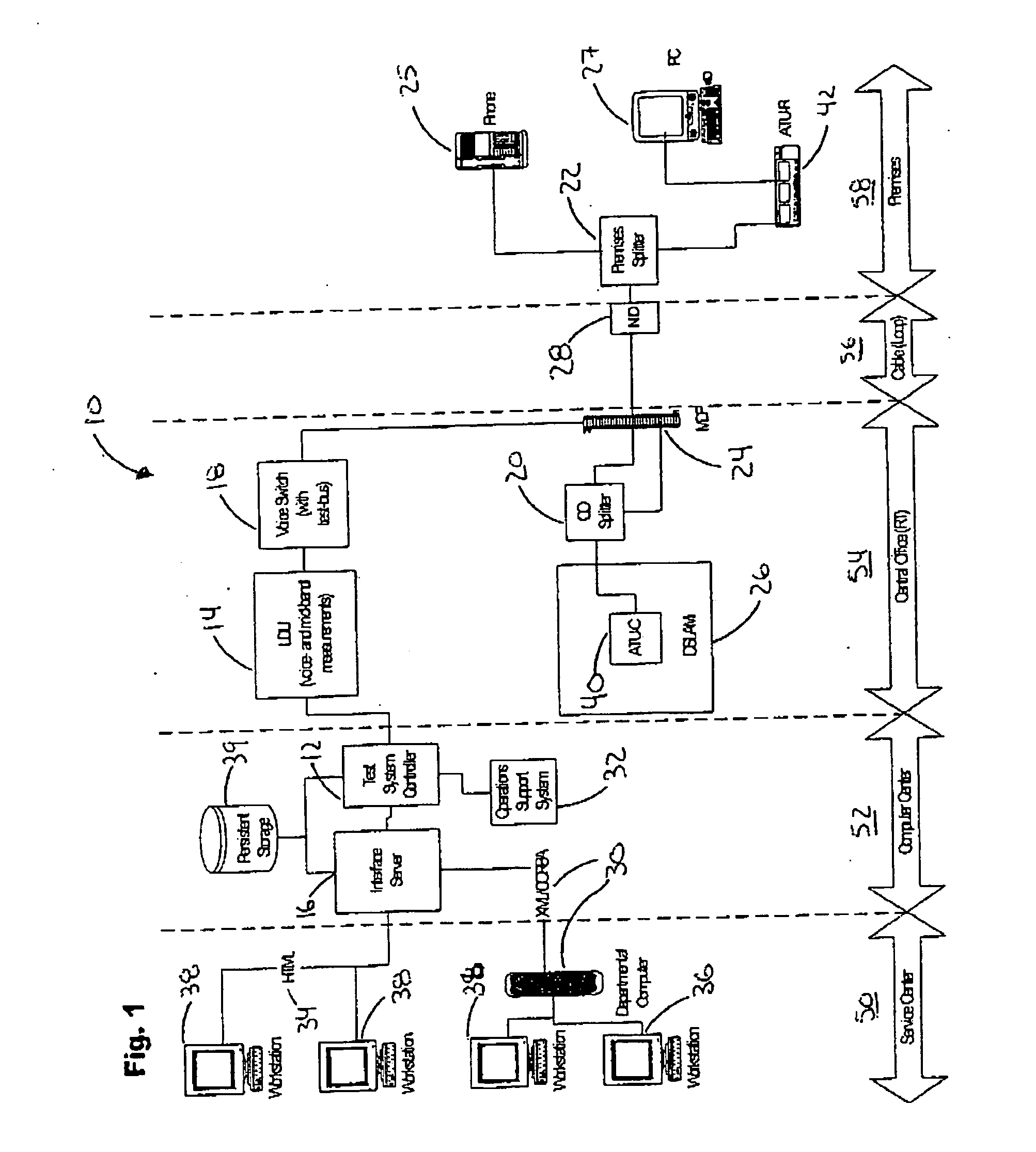
[0027] The written description uses a large number of acronyms to refer to various services and system components. For purposes of this description, selected acronyms therefore will be defined as follows:

DSL—Digital Subscriber Line

ADSL—Asymmetrical Digital Subscriber Line

HDSL—High data rate Digital Subscriber Line

VDSL—Very high data rate Digital Subscriber Line

xDSL—Generic class of Digital Subscriber Line Services

ATU-C—ADSL Terminal Unit-Central Office

ATU-R—ADSL Terminal Unit-Remote

RT—Remote Switching Unit

CO—Central Office

DSLAM—Digital Subscriber Lim Access Multiplexer

TAM—Test Access Matrix

MDF—Main Distribution Frame

...


PUM


Abstract

A system and method for performing DSL assessments of a telephone line along a prescribed test path is disclosed. The disclosed system includes a loop diagnostic test unit adapted for testing said telephone line using narrow-band and mid-band frequency test signals; a test system controller and a test system server to provide the DSL assessments to a user via an appropriate interface. In addition, the disclosed methods include the basic steps of: accessing the telephone line along the test path that includes selected hardware such as a voice switch test bus, central office splitter, service provider instruments and terminations; ascertaining various line characteristics along the test path using mid-band and narrow-band frequency signals; analyzing the line characteristics to identify line conditions that affect DSL service; and determining the impact of the line conditions on DSL service.

Description

CROSS REFERENCE TO RELATED APPLICATIONS [0001] (None) STATEMENT REGARDING FEDERALLY SPONSORED RESEARCH [0002] (None) SEQUENCE LISTING OR COMPUTER PROGRAM [0003] (None) BACKGROUND [0004] The present invention relates to a method for assessing DSL capability of telephone lines, and more particularly, a DSL test method that employs test signals in both narrow band frequency ranges and mid band frequency ranges along a selected test path of a telephone line to identify line characteristics and line conditions that could affect DSL service on the telephone line. [0005] With the explosion in the growth of Internet usage among both businesses and households, telephone companies have been pressured to provide affordable, high bandwidth access that will support high-speed multimedia services, such as video on demand, high speed Internet access, and video conferencing. To meet this demand, telephone companies are increasingly turning to digital subscriber line (DSL) technology. As used herein...

Claims


Application Information

Patent Timeline
Patent Type & Authority Applications(United States)
IPC IPC(8): H04M1/24
CPCH04M3/306H04M3/2209
Inventor WARNER, RODERICKAFZAL, MOHAMMADBAUER, FRANKROSEN, JOSEPH
Owner TOLLGRADE COMM INC
Why Eureka
Try Eureka