Accessing results of network diagnostic functions in a distributed system

a distributed system and network diagnostic technology, applied in the field of network testing, can solve the problems of network communication, general experience, and large communication bandwidth demand, and achieve the effect of increasing flexibility

Active Publication Date: 2005-03-03
VIAVI SOLUTIONS INC
View PDF10 Cites 45 Cited by
  • Summary
  • Abstract
  • Description
  • Claims
  • Application Information

AI Technical Summary

Benefits of technology

[0023] Subsequent to initiation of the diagnostic function, a monitoring computer system sends a results request directly to an allocated resource. The monitoring computer may be the requesting computer system or may be some other computer system that is network connectable to the chassis. The chassis receives the results request at the allocated resource and identifies results corresponding to the network diagnostic function. The chassis returns identified results to the monitoring computer system. The monitoring computer system receives the results directly from the allocated resource and presents the received resources at a user-interface. Accordingly, since a requesting and monitoring computer system can differ, results of network diagnostic functions can be accessed with increased flexibility.

Problems solved by technology

Computer and data communications networks continue to proliferate due to declining costs, increasing performance of computer and networking equipment, and increasing demand for communication bandwidth.
However, as communication networks have increased in size, speed, and complexity, they have become increasingly likely to develop a variety of problems that, in practice, are often difficult to diagnose and resolve.
Communication network problems are of particular concern in light of the continuing demand for high levels of network operational reliability and for increased network capacity.
The problems generally experienced in network communications can take a variety of forms and may occur as a result of a variety of different circumstances.
Examples of circumstances, conditions and events that may give rise to network communication problems include the transmission of unnecessarily small frames of information, inefficient or incorrect routing of information, improper network configuration and superfluous network traffic, to name just a few.
These problems are aggravated by the fact that communication networks are continually changing and evolving due to growth, reconfiguration and introduction of new network topologies and protocols.
For example, data transmission faults or errors, or performance errors, known generally as problem conditions, may be diagnosed by examining the captured data that is related to the problem.
Results of this comparison can reveal errors within the bit sequence.
However, if an test computer system malfunctions after a network test is initiated, it can be difficult, if not impossible, to access test results.
Thus, when the test computer system malfunctions, it can be difficult for administrators or testers at other computer systems to stop the network test.
In fact, there may be no way to stop the network test without removing power form the test chassis and / or testing module.
Unfortunately, removing power from a test chassis can cause other network tests to stop thereby inconveniencing other administrators and / or testers that have initiated these other network tests.
Further, since test results are transferred to the test computer system (over the established connection), there may be no way to view or store the test results at other computer systems.
Returning to an office computer system can inconvenience an administrator or tester that must return to the office computer system from another location (e.g., at home) to access test results.

Method used


Image

  • Accessing results of network diagnostic functions in a distributed system
  • Accessing results of network diagnostic functions in a distributed system
  • Accessing results of network diagnostic functions in a distributed system

Examples


Embodiment Construction

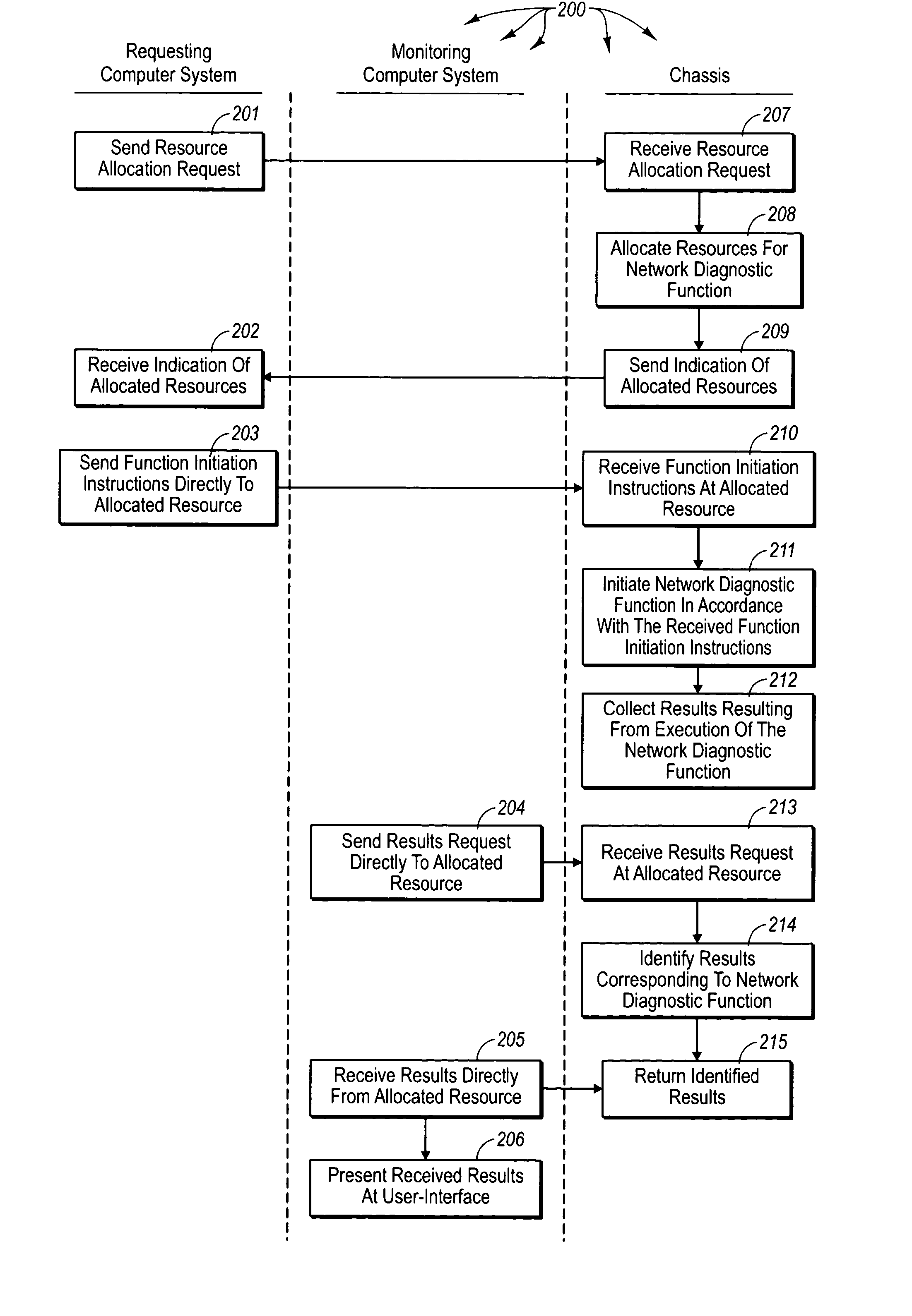
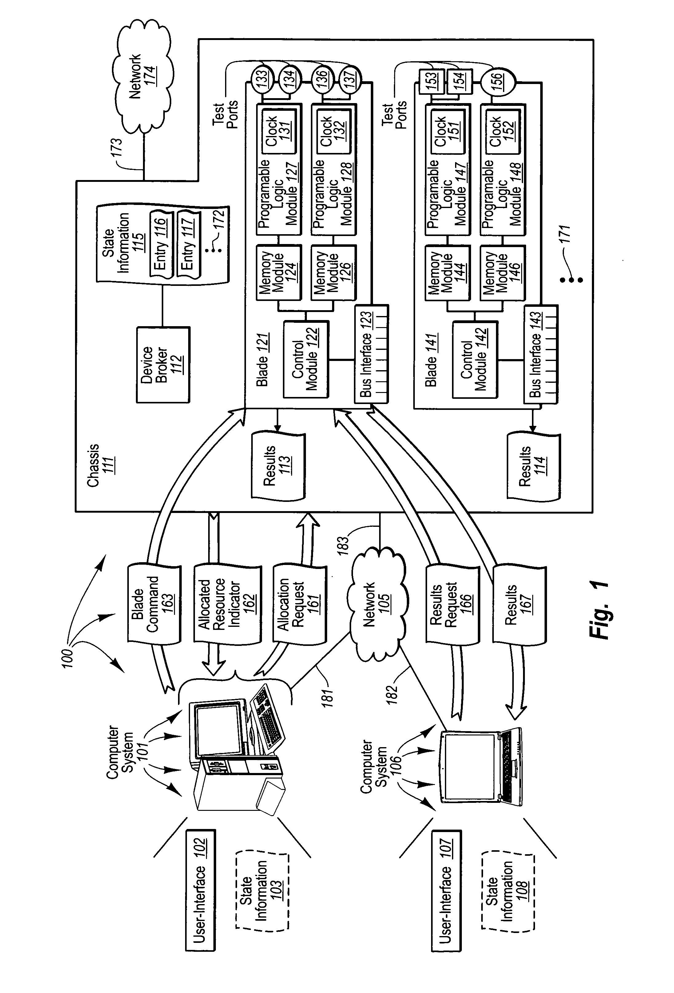
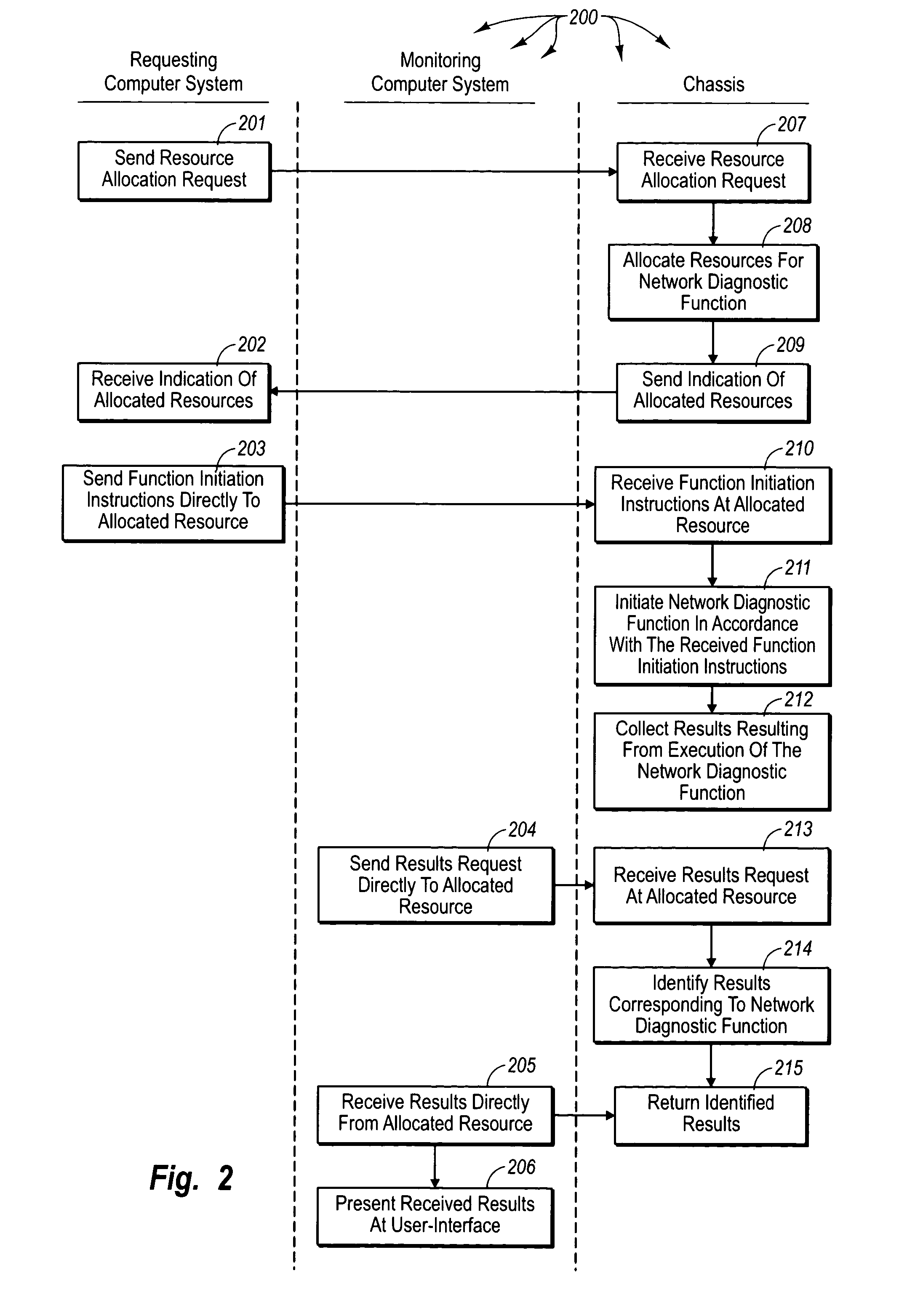
[0031] The principles of the present invention provide for accessing results of network diagnostic functions in a distributed system. A chassis contains one or more network diagnostic modules. In some embodiments, network diagnostic modules can include one or more programmable logic modules (e.g., one or more Field Programmable Gate Arrays (“FPGAs”)) with circuitry for implementing any of a plurality of different network diagnostic functions (e.g., network analyzer, jammer, generator, bit rate error test, etc). Each programmable logic module controls one or more test ports that provide interfaces for different physical configurations (e.g., Gigabit Ethernet, Fiber Distributed Data Interface, Fiber Channel, etc.) and that can interoperate with the programmable logic module to implement a selected network diagnostic function. It may be that a network diagnostic module is included in a printed circuit board (hereinafter referred to as a “card” or “blade”) that is inserted into an appro...


PUM


Abstract

The principles of the present invention extend to accessing results of network diagnostic functions in a distributed system. A chassis allocates resources for performing a network diagnostic function directly to requesting computer system. The requesting computer system communicates directly with the allocated resources to initiate the network diagnostic function. The network diagnostic test continues to execute even if the requesting computer system subsequently malfunctions. Collected test results are stored at the chassis such that any network connectable computer system can access the collected test results. A monitoring computer system (which may or may not be the requesting computer system) requests collected test results corresponding to the network diagnostic function. The chassis identifies appropriate test results and returns the results to the monitoring computer system.

Description

1. CROSS REFERENCE TO RELATED APPLICATIONS [0001] The present application claims priority to U.S. Provisional Patent Application Ser. No. 60 / 498,249 entitled “Accessing Results Of Network Diagnostic Functions In A Distributed System” filed Aug. 26, 2003, which is hereby incorporated by reference.BACKGROUND OF THE INVENTION [0002] 1. The Field of the Invention [0003] The present invention relates to network testing, and more specifically, to accessing results of network diagnostic functions in a distributed system. [0004] 2. Background and Relevant Art [0005] Computer and data communications networks continue to proliferate due to declining costs, increasing performance of computer and networking equipment, and increasing demand for communication bandwidth. Communications networks—including wide area networks (“WANs”) and local area networks (“LANs”)—allow increased productivity and utilization of distributed computers or stations through the sharing of resources, the transfer of voi...

Claims


Application Information

Patent Timeline
Patent Type & Authority Applications(United States)
IPC IPC(8): G06F15/173H04L12/24
CPCH04L12/2697H04L43/50H04L41/0806
Inventor YANG HAROLD (HAORAN)
Owner VIAVI SOLUTIONS INC
Why Eureka
Try Eureka