Eureka AIR delivers breakthrough ideas for toughest innovation challenges, trusted by R&D personnel around the world.

Silane process chamber with double door seal

Inactive Publication Date: 2007-10-04
MOFFAT WILLIAM A +2
View PDF17 Cites 13 Cited by
  • Summary
  • Abstract
  • Description
  • Claims
  • Application Information

AI Technical Summary

Benefits of technology

[0013] A process chamber for the coating of substrates with silanes with a double door seal. The double door seal may have a cavity between the seals which may be evacuated or pressurized, including with an inert gas. An apparatus for the coating of substrates comprising a process oven, a gas plasma subsystem, a metered chemical withdrawal subsystem, a vacuum subsystem, a vaporization subsystem, and a double door seal. A process oven utilizing a double sealed door with pressurized inert gas between the seals to reduce oxygen contamination and risks associated with silane processes.

Problems solved by technology

Many of the chemicals now used are silanes which are significantly more sensitive to oxygen with regard to the success of the process, and which also have a significant risk associated with the meeting of the silane vapor with oxygen.
Processes involving the preheating of deposition chemicals, especially silanes, have the risk that if the deposition chemicals are raised to a temperature above their auto-ignition temperature, exposure to oxygen can result in fire or explosion.
With some chemical vapors, the auto-ignition temperature may be below ambient temperature, and the risk of fire or explosion in the presence of oxygen may exist even without preheating.
In addition to the risk of explosion, ignition of silanes within the process chamber may leave residues, and block inlet lines, in a way that renders the chamber useless.
In addition to the safety risks mentioned above, the introduction of oxygen into silane coating processes may alter the process in an unwanted way.
Also, these gasses may be passed through a purifier which further reduces the oxygen content.

Method used


Image

  • Silane process chamber with double door seal
  • Silane process chamber with double door seal
  • Silane process chamber with double door seal

Examples


Embodiment Construction

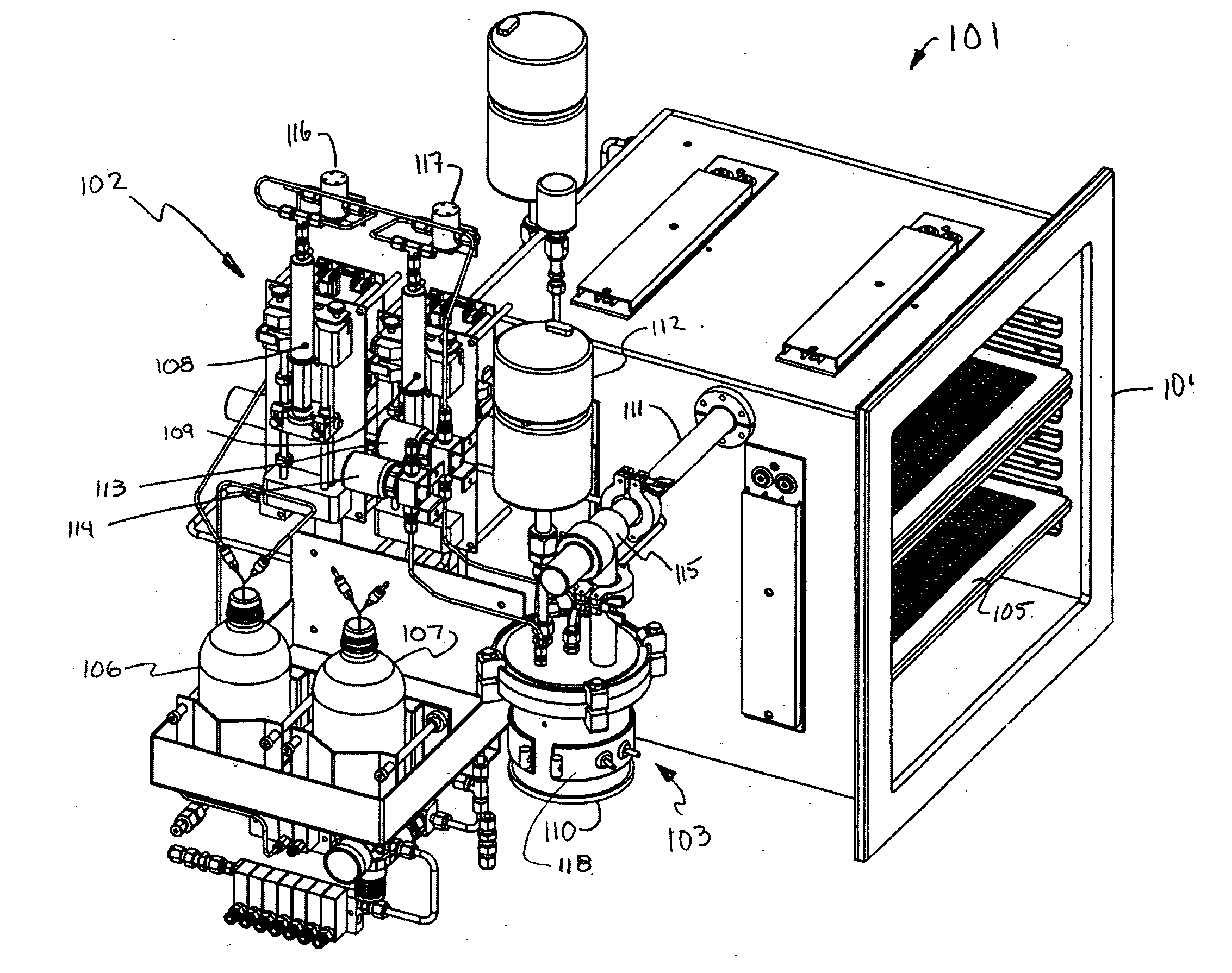
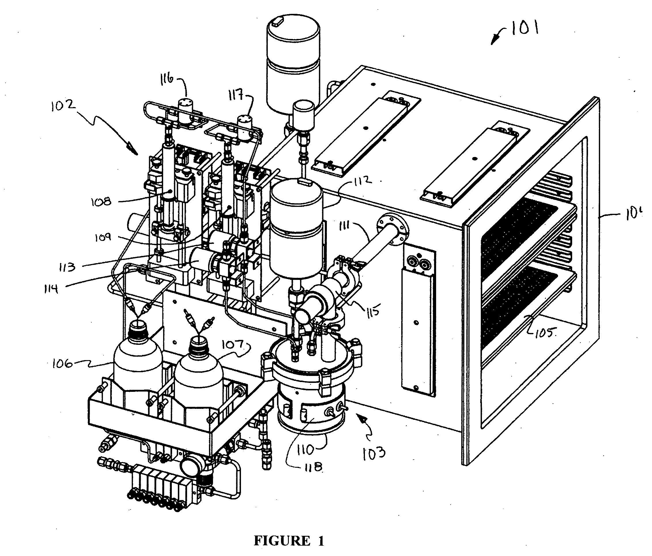
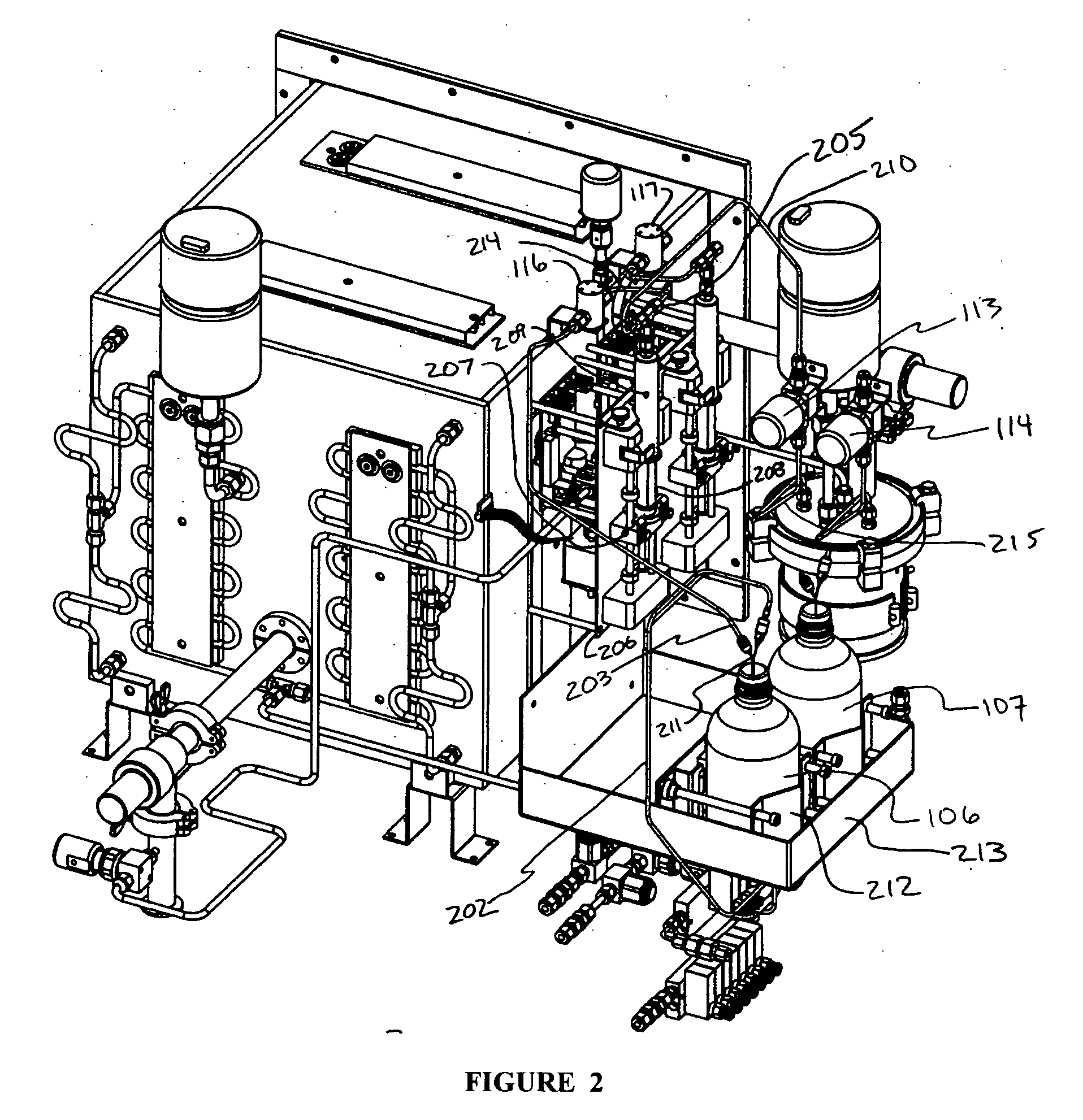
[0031] In one embodiment of the present invention, as seen in FIG. 1, chemical vapor deposition apparatus 101 has a fluid input portion 102, a vaporization portion 103, and a process oven 104. Process oven 104 may be controlled with regard to both temperature and pressure. Fluid reservoirs 106, 107 provide the chemicals for the fluid input portion 102. Fluid reservoirs 106, 107, may be manufacturer's source bottles in some embodiments. Fluid reservoirs may contain the same fluid, allowing for the easy replacement of one reservoir if empty without disruption of the deposition process, or may contain separate chemicals. In some applications, water may be used as one of the chemicals in order to facilitate some rehydration of the substrate.

[0032] Chemicals in the fluid reservoirs 106, 107, are withdrawn into fluid input portion 102 by syringe pumps 108, 109. Although syringe pumps are used in this embodiment, other methods of withdrawal may be used, including peristaltic pumps and oth...


PUM

PropertyMeasurementUnit
Pressureaaaaaaaaaa
Vacuumaaaaaaaaaa

Abstract

A process chamber for the coating of substrates with silanes with a double door seal. The double door seal may have a cavity between the seals which may be evacuated or pressurized, including with an inert gas. An apparatus for the coating of substrates comprising a process oven, a gas plasma subsystem, a metered chemical withdrawal subsystem, a vacuum subsystem, a vaporization subsystem, and a double door seal. A process oven utilizing a double sealed door with pressurized inert gas between the seals to reduce oxygen contamination and risks associated with silane processes.

Description

CROSS-REFERENCE TO RELATED APPLICATIONS [0001] This application is a continuation in part of U.S. patent application Ser. No. 10 / 656,840 to Moffat et al., filed Sep. 5, 2003, which is hereby incorporated by reference. This application relates to U.S. patent application Ser. No. 10 / 843,774 to Moffat et al., filed May 11, 2004, which is hereby incorporated by reference. This application relates to U.S. patent application Ser. No. 10 / 695,633 to Moffat et al., filed Oct. 27, 2003, which is hereby incorporated by referenceBACKGROUND [0002] 1. Field of the Invention [0003] This invention relates to process chambers, and in particular to a process chamber and process for the safer and lower contamination coating of substrates involving vapors and vaporous silanes using a chamber with a double door seal. [0004] 2. Description of the Related Art [0005] The application of coatings onto substrates and other workpieces is required as a process step in many industrial fields. An example of such ...

Claims


Application Information

Patent Timeline
IPC IPC(8): C23C16/00B05D7/24
CPCB05D1/60C23C16/4409C23C16/45561B05D7/24
Inventor MOFFAT, WILLIAM A.MCCOY, CRAIGALLEN, STUART
Owner MOFFAT WILLIAM A
Why Eureka
Eureka Blog
Learn More