
Secondary battery of improved safety

a technology of safety and secondary batteries, applied in the direction of cell components, final product manufacturing, sustainable manufacturing/processing, etc., can solve the problems of thermal runaway phenomenon, battery fire or explosion, etc., and achieve the effect of preventing deformation of the depressed step region, low mechanical strength, and easy deformation

Active Publication Date: 2007-10-04
LG ENERGY SOLUTION LTD
View PDF1 Cites 29 Cited by
  • Summary
  • Abstract
  • Description
  • Claims
  • Application Information

AI Technical Summary

Benefits of technology

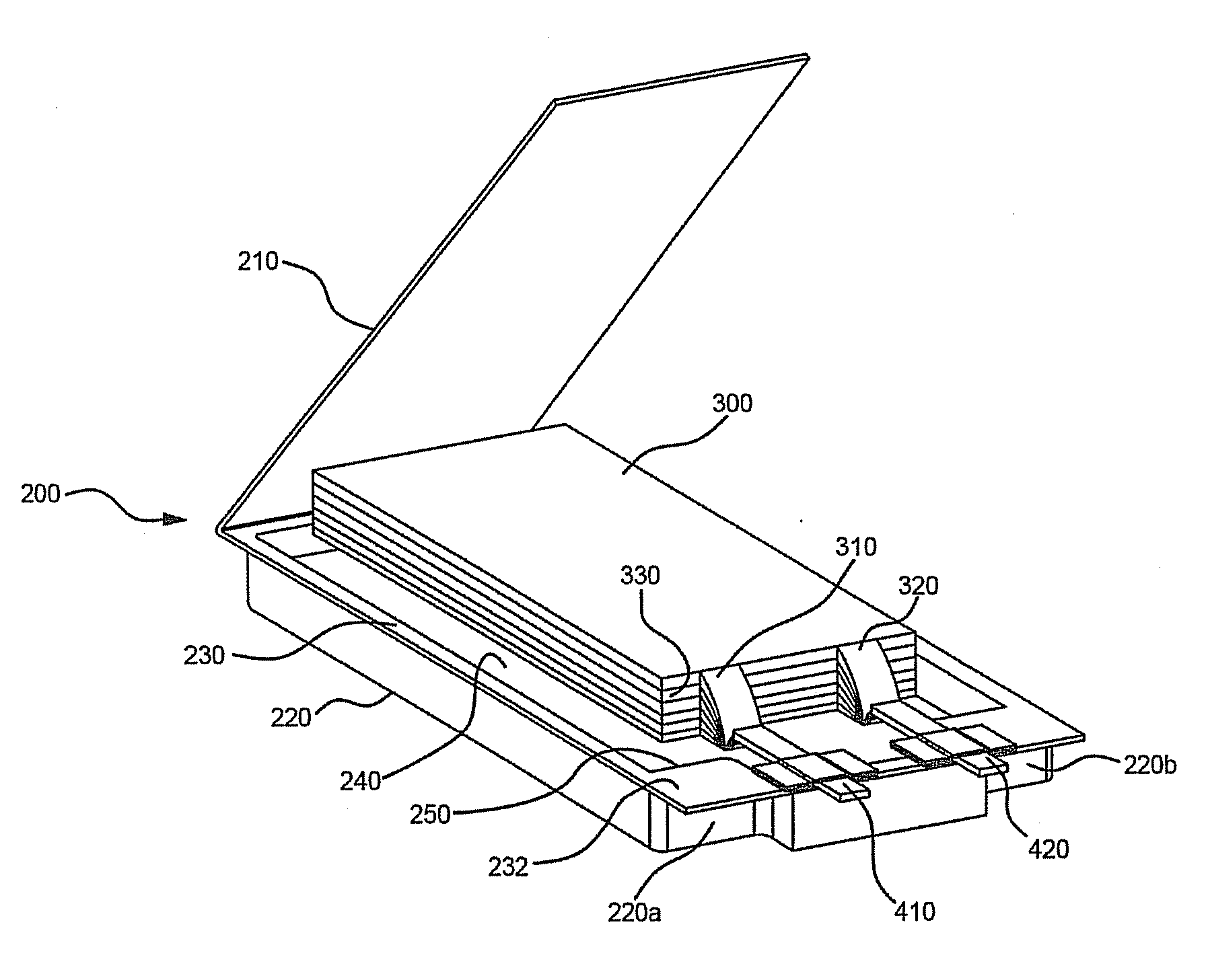
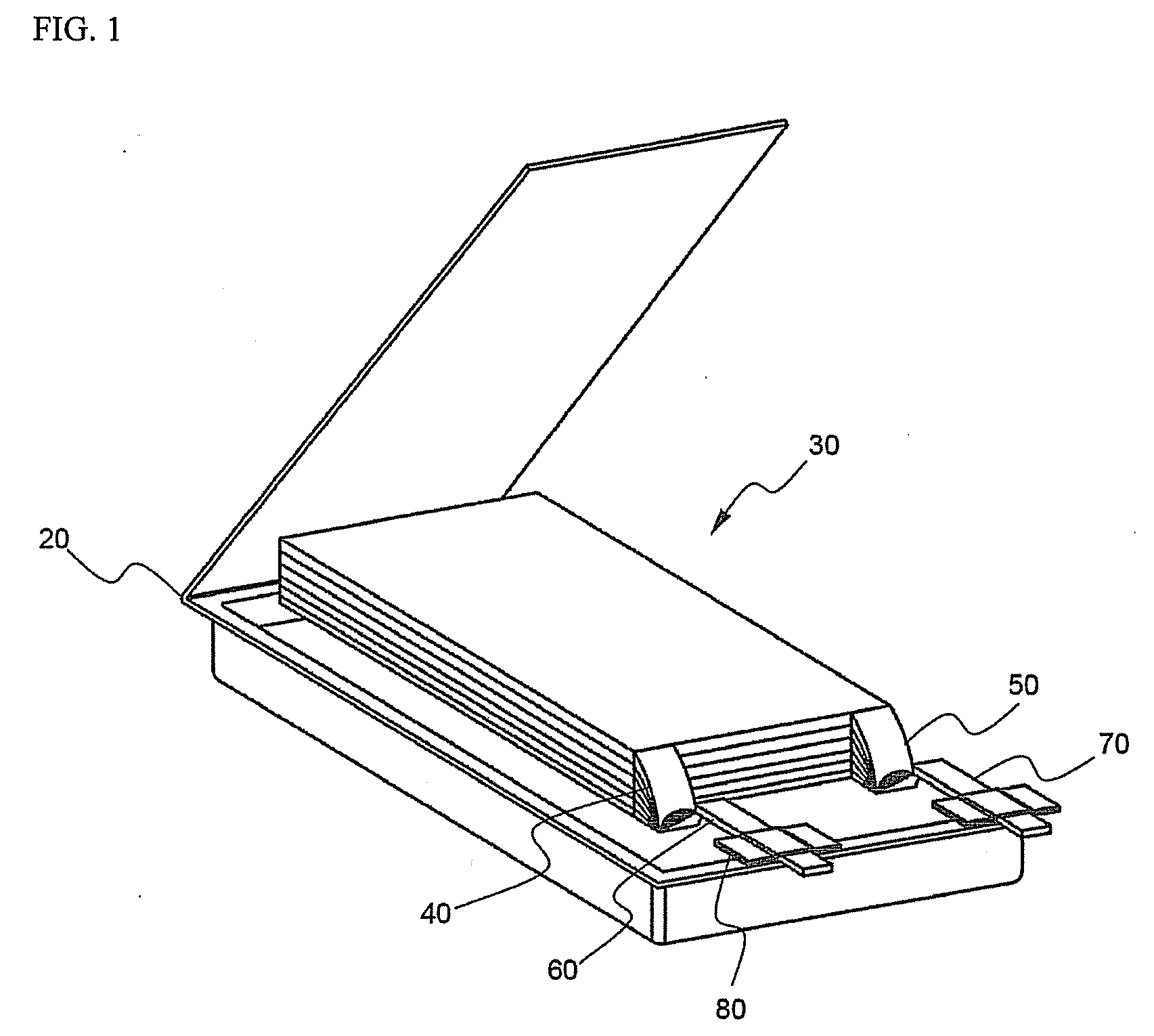
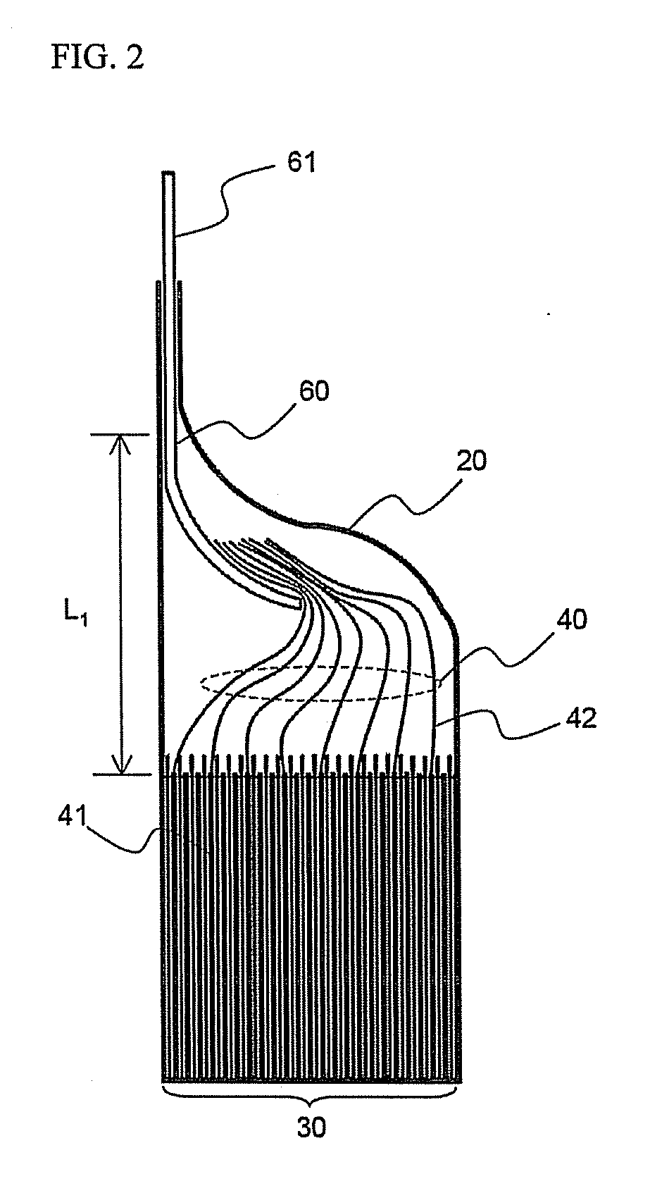
[0017]As a result of a variety of extensive and intensive studies and experiments to solve the problems as described above, the inventors of the present application have discovered that, in a secondary battery having an electrode assembly, which includes electrode taps-electrode lead coupling parts (V-form regions), mounted therein, when a receiving part of a battery case corresponding to the V-form regions is modified in a specific shape such that the electrode assembly can be brought into tight contact with the battery case, the V-form regions, which do not contribute to the capacity and the operation of the battery, are effectively utilized, and the shape of battery case is easily modified with the result that the occurrence of short circuits inside the secondary battery due to application of an external force to the secondary battery, for example, dropping of the secondary battery, is prevented, and therefore, the safety of the secondary battery is further improved. The present invention has been completed based on the above-mentioned discovery.
[0020]In the secondary battery, on the other hand, the electrode assembly is mounted in the battery case while the electrodes of the electrode assembly are stably located in position due to the depressed step formed at a predetermined region of the battery case. Consequently, even when the battery drops or an external force is applied to the battery, the movement of the electrodes in the electrode assembly is restrained, and therefore, the occurrence of short circuits inside the battery is prevented, and, ultimately, the safety of the battery is improved.
[0027]In the B structure, the depressed step is formed at the middle of the upper end of the receiving part of the battery case, and therefore, it is relatively easy to vertically bend the side sealing part such that the side sealing part can be brought into tight contact with the receiving part while the battery case is sealed after the electrode assembly is received in the receiving part so as to reduce the total size of the battery. Consequently, the B structure is preferred to the A structure.
[0030]More preferably, the thermal welding is also performed to the depressed step region when the battery case is sealed by the thermal welding. Since the battery case made of the laminate sheet has low mechanical strength, the battery case may be easily deformed when an external force is applied to the battery case. As a result, the depressed step region may be deformed when large pressure is applied to the depressed step region from the electrode assembly due to several causes. When the depressed step region of the battery case is thermally welded, on the other hand, such deformation of the depressed step region is fundamentally prevented, and therefore, the safety of the secondary battery is further improved.

Problems solved by technology

The occurrence of short circuits inside the battery due to dropping of the battery or application of an external force to the battery may act as a principal factor of explosion or catching fire of the battery.
When the interior temperature of the battery exceeds a critical temperature level due to the high resistance heat, the oxide structure of a cathode active material is collapsed, and therefore, a thermal runaway phenomenon occurs.
As a result, the battery may catch fire or explode.

Method used


Image

  • Secondary battery of improved safety
  • Secondary battery of improved safety
  • Secondary battery of improved safety

Examples


Embodiment Construction

[0041]Now, preferred embodiments of the present invention will be described in detail with reference to the accompanying drawings. It should be noted, however, that the scope of the present invention is not limited by the illustrated embodiments.

[0042]FIG. 4 is an exploded perspective view illustrating a pouch-shaped secondary battery according to a preferred embodiment of the present invention, FIG. 5 is a front see-through view illustrating the secondary battery of FIG. 4 in an assembled state, and FIG. 6 is a side see-through view illustrating the secondary battery of FIG. 4 in an assembled state.

[0043]Referring to these drawings, the pouch-shaped secondary battery 200 includes an electrode assembly 300 having cathode taps 310 welded to a cathode lead 410 and anode taps 320 welded to an anode lead 420, a battery case 200 for receiving the electrode assembly 300, and depressed steps 220a and 220b formed at upper end corners of the battery case 200.

[0044]The battery case 200 includ...


PUM


Abstract

Disclosed herein is a secondary battery having an electrode assembly received in a receiving part of a battery case, the electrode assembly being constructed in a structure in which pluralities of cathodes and anodes are stacked one on another while separators are disposed between the respective cathodes and anodes, and electrode taps extending from the stacked cathodes and anodes are coupled to electrode leads, wherein the receiving part of the battery case is provided at the outer upper end thereof with a depressed step such that at least a portion of the inner upper end of the receiving part of the battery case excluding the electrode taps-electrode lead coupling parts of the electrode assembly is in tight contact with the upper end of the electrode assembly.

Description

FIELD OF THE INVENTION[0001]The present invention relates to a secondary battery having improved safety, and, more particularly, to a secondary battery having an electrode assembly received in a receiving part of a battery case, the electrode assembly being constructed in a structure in which pluralities of cathodes and anodes are stacked one on another while separators are disposed between the respective cathodes and anodes, and electrode taps extending from the stacked cathodes and anodes are coupled to electrode leads, wherein the receiving part of the battery case is provided at the outer upper end thereof with a depressed step such that at least a portion of the inner upper end of the receiving part of the battery case is in tight contact with the upper end of the electrode assembly.BACKGROUND OF THE INVENTION[0002]As mobile devices have been increasingly developed, and the demand of such mobile devices has increased, the demand of batteries has also sharply increased as an ene...

Claims


Application Information

Patent Timeline
IPC IPC(8): H01M2/22H01M50/124H01M50/178H01M50/528H01M50/55H01M50/553H01M50/566
CPCH01M2/021H01M10/052H01M2/22H01M2/0275Y02E60/10H01M50/528Y02P70/50H01M50/124H01M50/178H01M50/55H01M50/553H01M50/566H01M50/20
Inventor LEE, HYANG MOKCHOI, BYUNGJINJANG, JUN HWANJUNG, HYUN-CHULSON, JEONGSAMAHN, CHANG BUMYUN, HYUNG KU
Owner LG ENERGY SOLUTION LTD
Learn More