Pedicle screw system with offset stabilizer rod

a stabilizer rod and pedicle screw technology, which is applied in the field of pedicle screw system with laterally offset stabilizer rod, can solve the problems of stacked components, extreme and debilitating pain of patients suffering from such conditions, and reducing nerve function, so as to achieve fast and easy use of the fixing system and method

Inactive Publication Date: 2007-10-04
AMEDICA A DELAWARE
View PDF13 Cites 68 Cited by
  • Summary
  • Abstract
  • Description
  • Claims
  • Application Information

AI Technical Summary

Benefits of technology

[0014] Each bone screw is captured within the respective anchor bracket with a threaded screw shank fastened securely into patient bone, and a head of the bone screw being positioned within the bracket. The head of the bone screw is generally spherical, as is an internal mating part-spherical surface of the anchor bracket surrounding a lower screw port or bore formed therein and through which the screw shank extends for connection to patient bone. This geometry allows for axial rotation of the bone screw during threaded installation into the vertebral bone, as well as multi-angle or poly-axial articulation and orientation of the bone screw relative to the anchor bracket. The bracket has a generally open top side to allow a suitable instrument or tool to engage and drive said bone screw into the vertebral body.
[0015] Each anchor bracket further defines a generally U-shaped and upwardly open channel or trough for accepting the elongated stabilization member such as a stabilizer rod. This U-shaped trough is defined by a wing or arm protruding laterally from the lower bore and the spherical screw head seated therein, thereby forming the trough in laterally offset relation to the associated and adjacent bone screw. The stabilizer rod is placed into and seated within the troughs of the anchor brackets associated with multiple pedicle screw units. Such rod placement is aided by the fact that the anchor brackets are able to undergo limited articulation about the heads of the respective bone screws. Additionally, the placement of the stabilizer rod is aided by the orientation of the U-shaped troughs, namely, by orienting the troughs to open in an upward or dorsal direction for quick and easy drop-in placement by the surgeon.
[0016] Subsequently, both the stabilization member and the bone anchors are secured in place relative to the associated brackets by a single securement member such as a locking or set screw fastened into each bracket. In the preferred embodiment, a set screw is threaded into an internally threaded upper bore formed in the top of the associated anchor bracket at a position overlapping or at least partially overlying both the stabilizer rod and the head of the associated bone screw. With this geometry, the set screw can be advanced within the upper bore to bear with parallel applied forces against both the bone screw and the stabilizer rod, substantially without pressing the stabilizer rod against the bone screw. As a result, the set screw bears against and retains the bone screw in place within the associated anchor bracket, thereby restricting or preventing relative motion between these components. In addition, the set screw independently bears against and retains the stabilizer rod in place within the same anchor bracket, thereby preventing or preventing relative motion between these components.
[0018] The thus-formed fixation device creates a low-profile implant due to the fact that the stabilization member is located at a laterally offset position at one side, and not on top of the associated bone screw. Additionally, since a single locking screw is used to secure these components in place relative to the anchor bracket, the fixation system and method are fast and easy to use. Finally, because all components, the bone screw with accompanying anchor bracket, stabilization member, and locking screw, are placed from the same approach, namely, generally a dorsal approach, only one incision is required, and that incision may be made smaller than otherwise required for a device having a laterally positioned stabilization member.
[0019] In accordance with a further aspect of the invention, the spinal fixation system of the present invention exhibits a secondary benefit due to the fact that the bone screw and stabilization member are independently locked by the common locking or set screw. More particularly, by utilizing the locking screw to retain the stabilizer rod without pressed engagement between the stabilizer rod and the associated bone screw, a semi-constrained system is created wherein, in one embodiment, the set screw can remain at least slightly disengaged from the associated bone screw to permit relative articulation between the bone screw and anchor bracket. Such articulation, limited by the constrained stabilizer rod, can provide appropriate spacing between the thus-constrained vertebral bodies while allowing for continuous load sharing of any bone grafting material used for fusion ingrowth relative to said vertebral bodies.

Problems solved by technology

Patients suffering from such conditions usually experience extreme and debilitating pain as well as diminished nerve function.
However, as will be set forth in more detail below, there are some disadvantages associated with current fixation devices.
However, one major drawback is that these components are stacked on top of each other, with the securing member on top of the stabilizing rod which is in turn disposed on top of the pedicle screw, all compressed in a stack within the receiving member or bracket.
This results in an assembled system having a significant vertical stack-up dimension which can lead to post-surgical irritation of muscle and other patient tissue.
Additionally, since the stabilizer rod must compress against the pedicle screw for proper fixation, there is no means or option for securing the stabilizer rod without also locking the pedicle screw in position relative to the receiving member.
While this results in reduced post-operative patient tissue irritation, there are disadvantages.
By way of example, in most embodiments, the elongated stabilizing member is loaded into the housing element from the side, thereby making it difficult to place intra-operatively and also requiring a surgical incision or increased size to accommodate such side-loading.
This use of multiple securing members undesirably increases the surgical complexity and thereby inherently increases the time needed to perform the surgical procedure.

Method used


Image

  • Pedicle screw system with offset stabilizer rod
  • Pedicle screw system with offset stabilizer rod
  • Pedicle screw system with offset stabilizer rod

Examples


Embodiment Construction

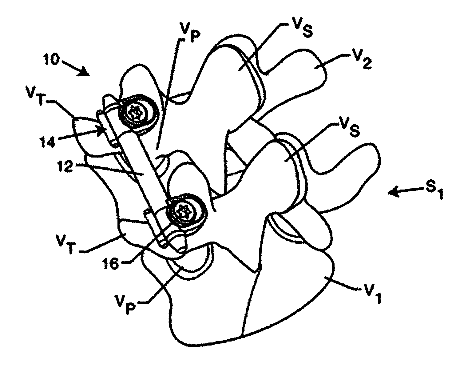
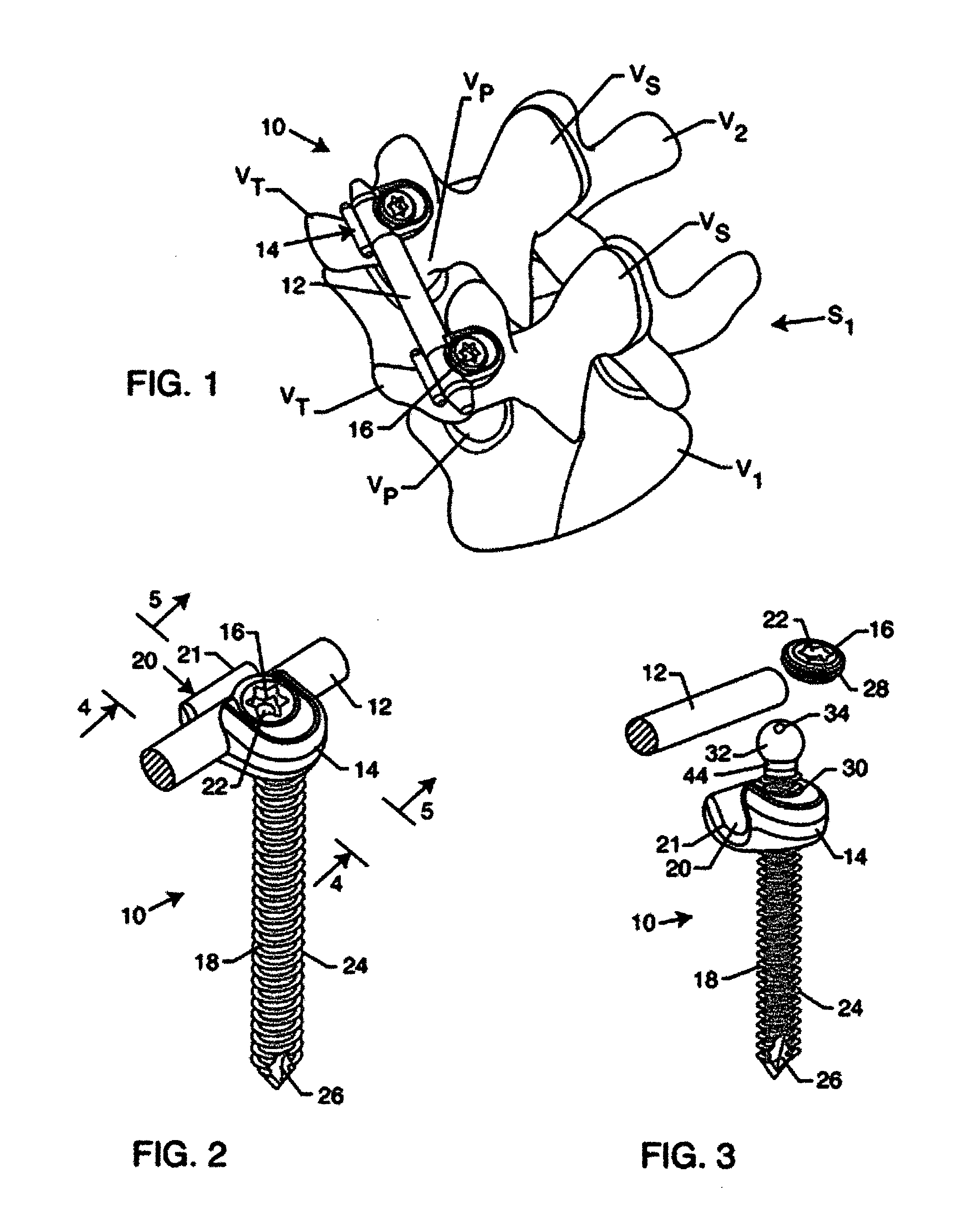
[0037] As shown in the exemplary drawings, an improved spinal fixation device referred to generally in FIGS. 1-5 by the reference numeral 10 is provided for attachment to at least a pair of adjacent patient bones such as spinal vertebrae S1 (FIG. 1) to maintain the skeletal structures in spaced relation while promoting bone ingrowth and fusion. In general, the improved fixation device 10 comprises a bio-compatible stabilization member such as an elongated stabilizer rod 12 providing a strong mechanical load bearing structure, with said rod 12 connecting with a plurality of bone screw units each including a bone screw 18 secured or anchored to the vertebrae S1.

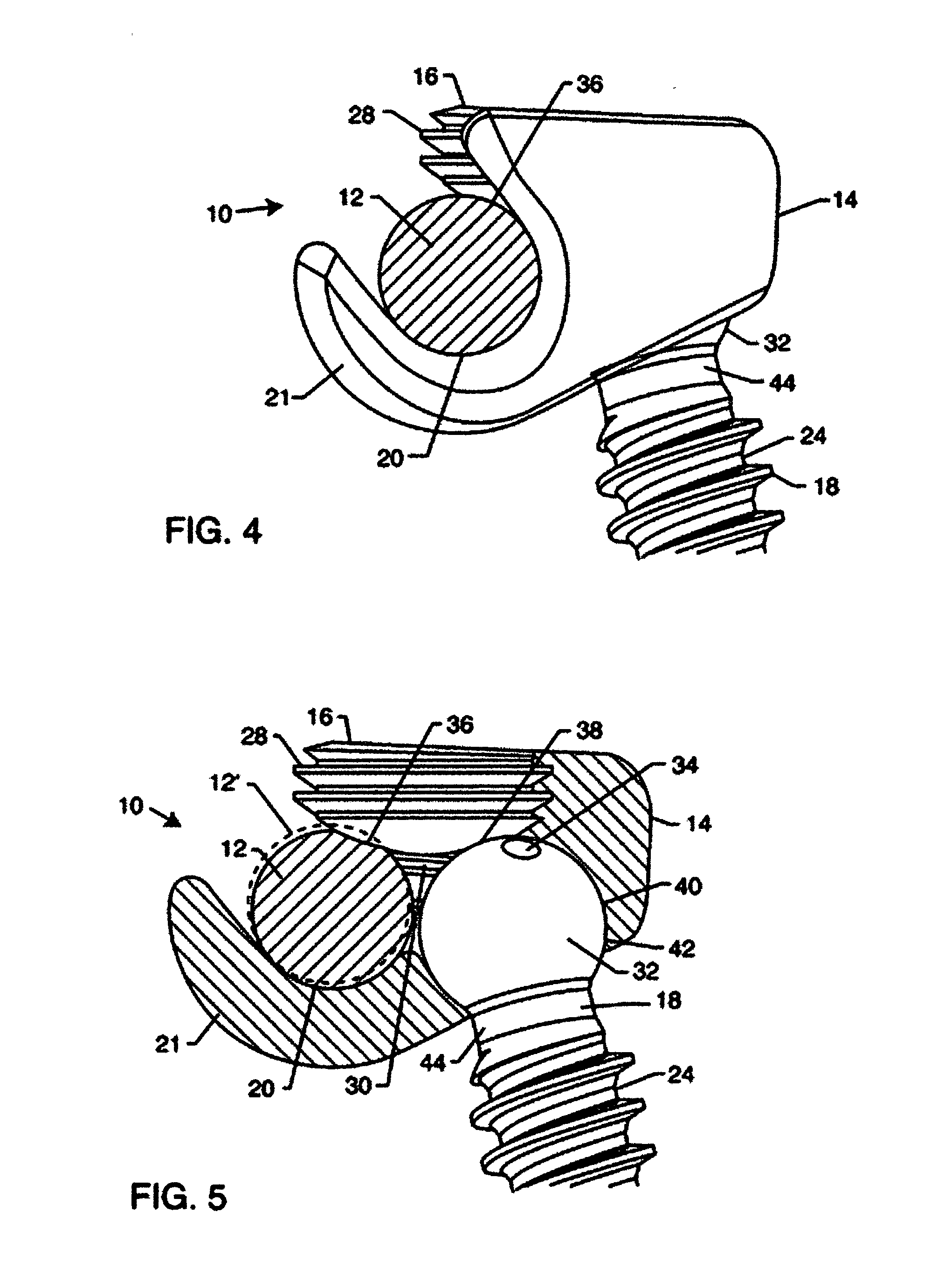
[0038] Each bone screw 18 comprises a threaded shank portion 24 for engaging and securely anchoring to patient bone. In the preferred embodiment, each bone screw 18 is manufactured from a high strength bio-compatible material, allowing for load carrying capabilities. Proximal to the threaded portion 24 is a screw head or head ...


PUM


Abstract

An improved pedicle screw system is provided with an offset stabilizer rod for the internal fixation of the spine. The pedicle screw system includes at least two multi-angle pedicle screw units adapted for anchored securement to patient bone, and an elongated stabilizer rod extending therebetween. Each pedicle screw unit includes a bone screw associated with an anchor bracket defining a laterally offset and upwardly open channel or trough for receiving and supporting the stabilizer rod. A securement member such as a set screw is fastened to the anchor bracket for compressively retaining the stabilizer rod within the bracket channel or trough. The securement member may also bear against the associated bone screw for compressively retaining the screw in position relative to the anchor bracket.

Description

BACKGROUND OF THE INVENTION [0001] This invention relates generally to improvements in devices and systems used for internal fixation of adjacent vertebral bodies of the spine. More specifically, this invention relates to an improved and relatively low profile pedicle screw system having a laterally offset stabilizer rod adapted for facilitated and highly stable implantation. [0002] The spinal column is a highly complex system of bones and connective tissues that provides support for the body and protects the delicate spinal column and nerves. The spinal column includes a series of vertebrae stacked one atop the other, whereby each vertebral body includes a relatively strong bone portion (cortical) forming the outside surface of the body and a relatively weak bone portion (cancellous) forming the center of the body. Situated between each vertebral body is an intervertebral disc formed from a non-bony, fibro-cartilage material that provides for cushioning and dampening of compressive...

Claims


Application Information

Patent Timeline
Patent Type & Authority Applications(United States)
IPC IPC(8): A61F2/44
CPCA61B17/7004A61B17/701A61B17/7041A61B17/7037A61B17/7034
Inventor BERRY, BRET M.
Owner AMEDICA A DELAWARE
Why Eureka
Try Eureka