Method of forming solder connection portions, method of forming wiring substrate and method of producing semiconductor device
a technology of wiring substrate and solder connection, which is applied in the direction of soldering apparatus, semiconductor/solid-state device details, non-printed masks, etc., can solve the problems of increasing the cost of producing semiconductor devices and mounting substrates, becoming difficult to form solder bumps relying on diameter differences, and achieving favorable and reliable production
- Summary
- Abstract
- Description
- Claims
- Application Information
AI Technical Summary
Benefits of technology
Problems solved by technology
Method used
Image
Examples
first example
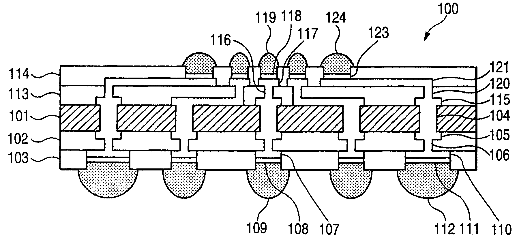
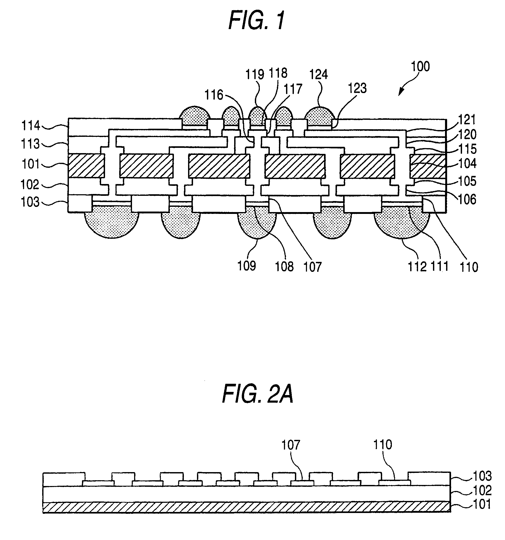
[0039]FIG. 1 is a sectional view schematically illustrating the structure of a wiring substrate produced by the method (described later) of forming solder connection portions according to a first embodiment of the invention.
[0040]Referring to FIG. 1, a wiring substrate (mounting substrate) 100 has a core substrate 101 made of, for example, a prepreg member, and a plurality of via-plugs 104 so as to penetrate through the core substrate 101.
[0041]Pattern wirings 105 connected to the via-plugs 104 are formed on a first surface of the core substrate 101, and pattern wirings 115 connected to via-plugs 104 are similarly formed on a second surface of the core substrate on the side opposite to the first surface.
[0042]Further, an insulating layer 102 is formed so as to cover the pattern wirings 105, and via-plugs 106 are formed in the insulating layer 102 so as to be connected to the pattern wirings 105. Moreover, electrode pads 107, 110 connected to the via-plugs 106 are formed on the insul...
second embodiment
[0071]FIG. 3 is a sectional view schematically illustrating a semiconductor device 200 formed by the method of producing a semiconductor device according to a second embodiment of the invention.
[0072]Referring to FIG. 3, the semiconductor device 200 includes a semiconductor chip 201 having electrode pads 203, 205 formed by a known method. A solder resist layer 202 is formed surrounding the electrode pads 203 and 205. Solder connection portions (solder bumps) 204, 206 are formed on the electrode pads 203 and 205, the solder connection potions (solder bumps) 204, 206 being formed by the method of forming solder connection portions of the first or second embodiment.
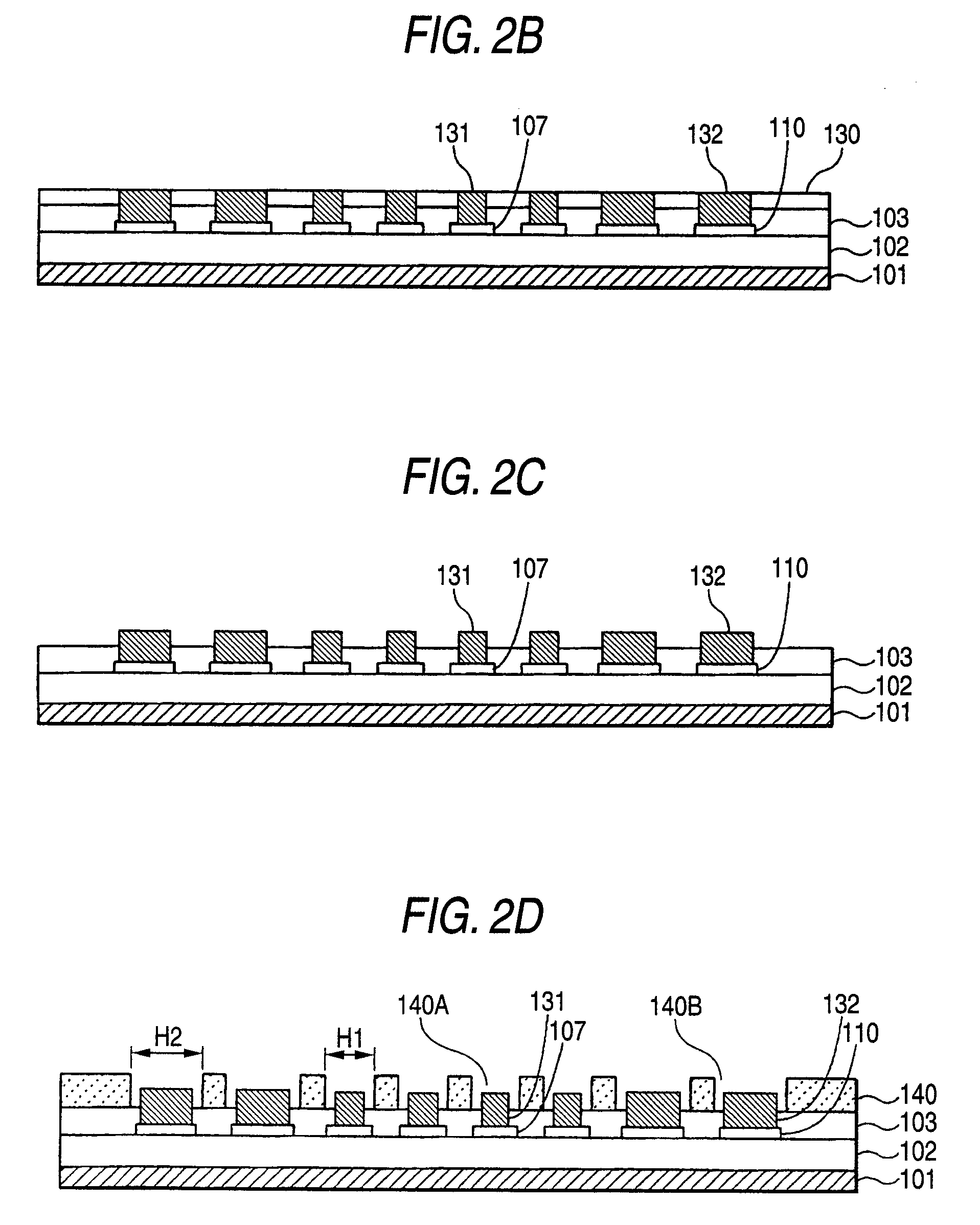
[0073]The solder connection portions 204, 206 are formed by the method illustrated in the first embodiment (FIGS. 2A to 2K).
[0074]In this case, the electrode pads 203 correspond to the electrode pads 107, and the electrode pads 205 correspond to the electrode pads 110. Further, the solder connection portions 204 correspond t...
third embodiment
[0076]FIG. 4 is a view of a semiconductor device 300 obtained by flip-chip-mounting the semiconductor device (semiconductor chip) 200 described in the second embodiment on the wiring substrate 100 described in the first embodiment. A semiconductor device can be thus formed by mounting the semiconductor device (semiconductor chip) having a plurality of solder connection portions of different sizes on the wiring substrate having a plurality of solder connection portions of different sizes. Further, when the semiconductor device 200 is mounted in the above structure, the solder connection portions (solder bumps) may be formed on both the wiring substrate 100 side and the semiconductor device 200 side, or may be formed on either side only.
PUM
| Property | Measurement | Unit |
|---|---|---|
| size | aaaaa | aaaaa |
| diameter | aaaaa | aaaaa |
| sizes | aaaaa | aaaaa |
Abstract
Description
Claims
Application Information
 - R&D
- Intellectual Property
- Life Sciences
- Materials
- Tech Scout
- Unparalleled Data Quality
- Higher Quality Content
- 60% Fewer Hallucinations
Browse by: Latest US Patents, China's latest patents, Technical Efficacy Thesaurus, Application Domain, Technology Topic, Popular Technical Reports.
© 2025 PatSnap. All rights reserved.Legal|Privacy policy|Modern Slavery Act Transparency Statement|Sitemap|About US| Contact US: help@patsnap.com


