Motor with reduction gear

a technology of motors and gears, applied in the direction of vehicle maintenance, vehicle cleaning, transportation and packaging, etc., to achieve the effect of simplifying the assembly work

Inactive Publication Date: 2007-10-11
MITSUBA CORP
View PDF2 Cites 4 Cited by
  • Summary
  • Abstract
  • Description
  • Claims
  • Application Information

AI Technical Summary

Benefits of technology

[0022]According to above item (3), since the gear cover can be formed in a flat plate shape, a process by pressing etc. can be faci...

Problems solved by technology

Therefore, there is such a problem that an impact force due to inertia caused by the...

Method used


Image

  • Motor with reduction gear
  • Motor with reduction gear
  • Motor with reduction gear

Examples


Embodiment Construction

[0028]Hereinafter, embodiments of the present invention will be described based on the accompanying drawings.

[0029]In the present embodiment, a motor with a reduction gear according to the present invention is constructed as a wiper motor used in a rear wiper device.

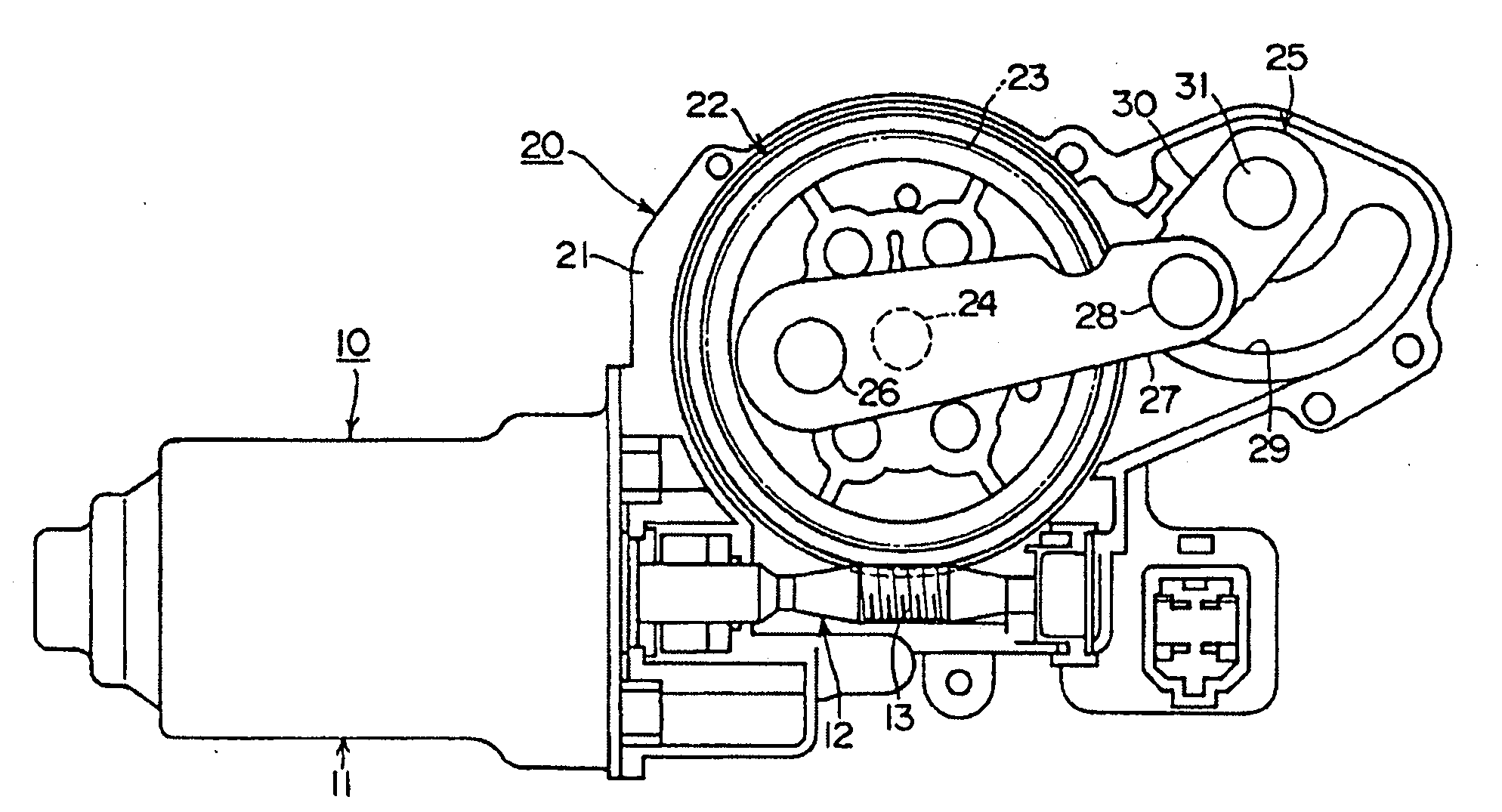
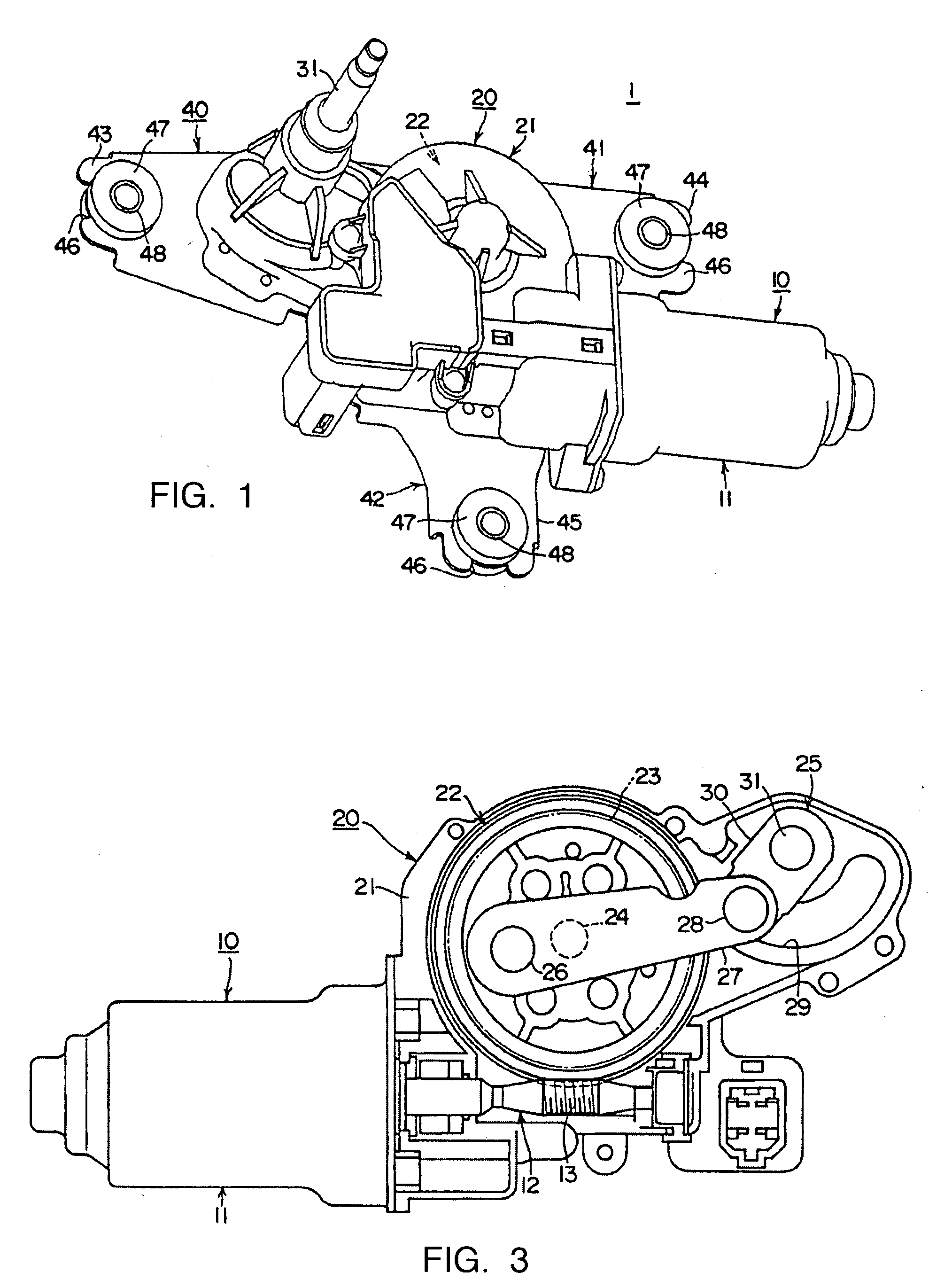
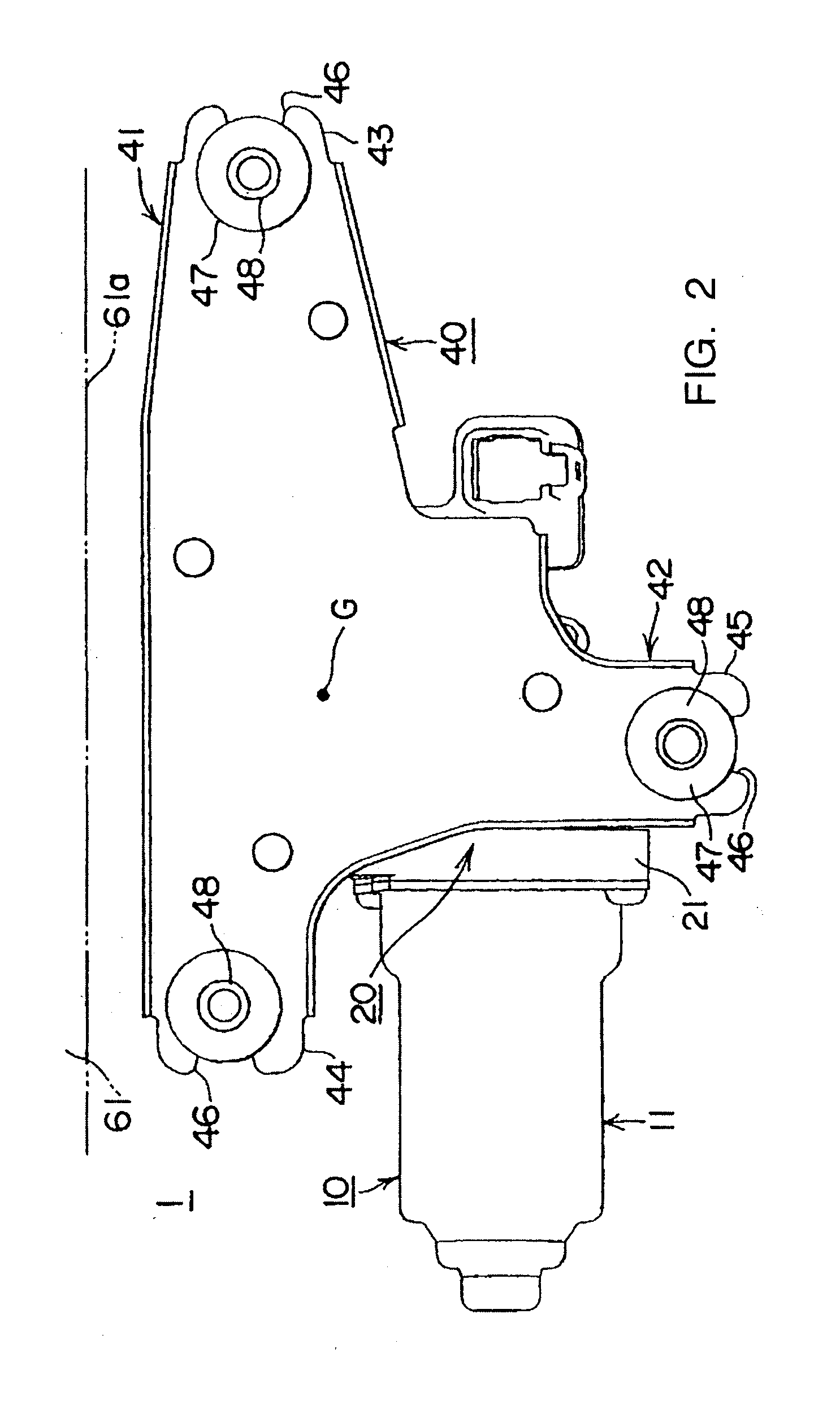
[0030]As shown in FIG. 1, a wiper motor 1 includes a motor part 10 having an electric motor 11, and a gear part 20 having a worm reduction gear 22 as a reduction gear. The motor part 10 and the gear part 20 are adjacently disposed and are fastened by bolts.

[0031]As shown in FIG. 3, a rotation axis (armature shaft) of the electric motor 11 is inserted into a gear case 21 having a bottom portion of the gear part 20 to be rotatably bridged therebetween. A worm 13 is formed on a middle portion of a rotation axis 12.

[0032]A worm wheel 23 of the worm reduction gear 22 is engaged with the worm 13. The worm wheel 23 is disposed in the same plane as that of the rotation axis 12.

[0033]A wheel shaft 24 as an output shaft of the wor...


PUM


Abstract

A wiper motor which can prevent an impact force from greatly acting on attaching parts is provided. A gear cover formed in a substantially T-plate shape is fastened to an opening of a gear case of the wiper motor used in a rear wiper device so as to cover a worm reduction gear and a crank device. A first attaching part and a second attaching part are formed at both end portions of a first band-shaped part of a T-shaped longitudinal member of the gear cover so as to have a relation to sandwich a wiper shaft therebetween. A third attaching part is formed at a tip portion of a second band-shaped part crossing the first band-shaped part in a T shape so as to have a relation to sandwich a rotation axis of an electric motor therebetween and face the second attaching part. A gravity center of the motor part and the gear part is arranged within an area of a triangle formed by the first attaching part, the second attaching part, and the third attaching part.

Description

CROSS-REFERENCE TO RELATED APPLICATIONS[0001]Applicant hereby claims foreign priority benefits under U.S.C. § 119 from Japanese Patent Application No. 2006-092511 filed on Mar. 29, 2006, the contents of which are incorporated by reference herein.TECHNICAL FIELD OF THE INVENTION[0002]The present invention relates to a motor with a reduction gear and more specifically to an attaching structure of the motor with a reduction gear, for example, to a technique effectively used in a rear wiper device of an automobile.BACKGROUND OF THE INVENTION[0003]The wiper motor used in the rear wiper device of the automobile includes a wiper motor comprising a motor part having an electric motor, a gear part having a reduction gear which is housed in a gear case coupled to the motor part and deaccelerates rotation of a rotation axis of the electric motor to convert the rotation to an oscillating motion and to transmit it to a wiper shaft, and a gear cover covering an opening of the gear case.[0004]When...

Claims


Application Information

Patent Timeline
IPC IPC(8): F16H57/04B60S1/08H02K7/116
CPCB60S1/0438Y10T74/2186B60S1/583
Inventor TAKADA, SADAKI
Owner MITSUBA CORP
Why Eureka
Try Eureka