Vehicle Steering System And Assembling Method Thereof

a steering system and vehicle technology, applied in the direction of electrical steering, anti-theft devices, transportation and packaging, etc., can solve the problems of complicated assembly work of divided parts, inability to form large diameter key lock collars, and increase the number of parts, so as to facilitate the assembly of worm wheels, and easy to fit the key lock collar

Inactive Publication Date: 2007-10-11
NSK LTD
View PDF9 Cites 4 Cited by
  • Summary
  • Abstract
  • Description
  • Claims
  • Application Information

AI Technical Summary

Benefits of technology

[0084] As described above, according to the first to tenth aspects of the invention, the large-diameter member (for example, worm wheel) is fixed or the key lock collar is fitted later to the steering shaft (input shaft and output shaft) having been inserted to the sensor coil. Accordingly, it is possible to easily fit the key lock collar having a diameter larger than the inner diameter of the sensor coil without increasing the number of parts.
[0085] Since the key lock collar is fitted later, the assembling method according to the invention is applicable to a steering shaft (input shaft) having a collapse structure.
[0086] Since the key lock collar is fitted later, the assembling method according to the invention is applicable to a steering system having a torque sensor mechanism without having a power assist mechanism. In this case, the large-diameter member is a yoke of a universal joint formed integrally with the output shaft.
[0087] According to the eleventh to twenty-second aspects of the invention, the driven gear is fitted later to the steering shaft to which the key lock collar has been fixed and which has been inserted to the sensor coil. Accordingly, it is possible to easily fit the key lock collar having a diameter larger than the inner diameter of the sensor coil without increasing the number of parts. It is possible to easily fit the worm wheel and to freely set the diameter of the key lock collar.
[0088] Since the driven gear is fitted later, the assembling method according to the invention is applicable to a steering shaft (input shaft) having a collapse structure.
[0089] Since the fitting portion of the driven gear to the steering shaft is hardly limited, a maker of the electric power steering system can perform a free design. Accordingly, an effect of design standardization can be expected.

Problems solved by technology

However, when a sensor unit is used, the key lock collar cannot be formed to have a large diameter due to the restriction by the inner diameter of the sensor coil.
However, as described in Patent Documents 1 to 3, when the input shaft of the electric power steering system is divided into two portions so as to fit the key lock collar of the antitheft device, the number of parts is increased and the assembly work of the divided parts is complicated, thereby causing increase in production cost.
However, when a coil is newly designed, considerable time is necessary and production cost is increased.

Method used


Image

  • Vehicle Steering System And Assembling Method Thereof
  • Vehicle Steering System And Assembling Method Thereof
  • Vehicle Steering System And Assembling Method Thereof

Examples


first embodiment

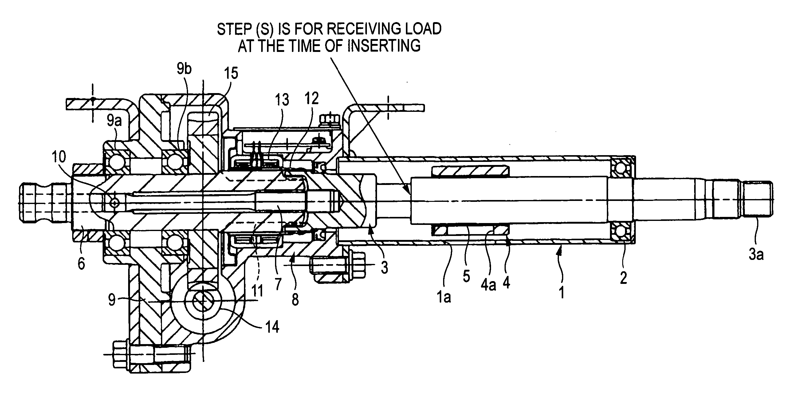
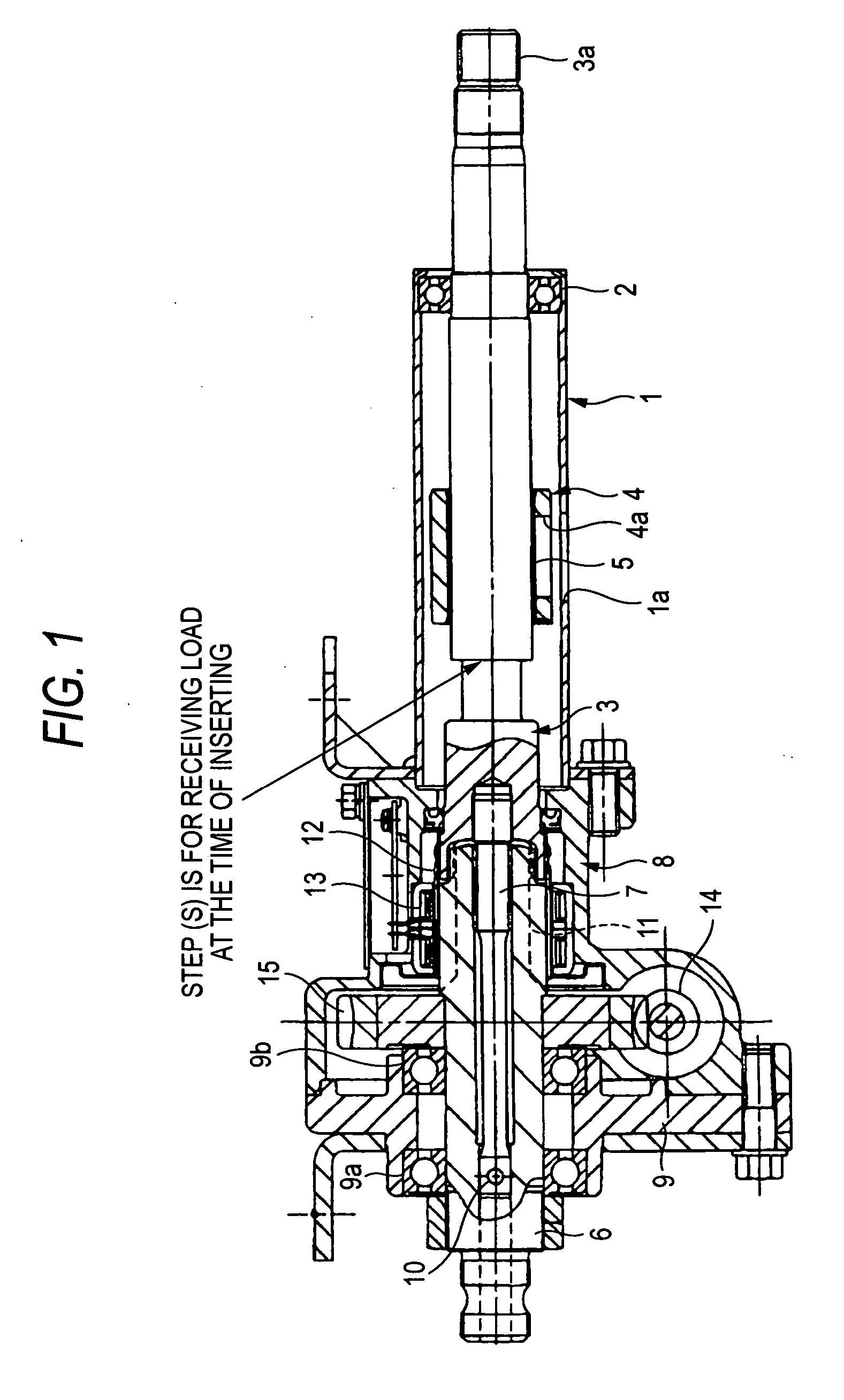
[0221]FIG. 1 is a longitudinal sectional view illustrating an electric power steering system according to a first embodiment of the invention.

[0222] An assembled electric power steering system according to this embodiment will be first described and a method of assembling the electric power steering system will be then described.

[0223] In the column-assisted electric power steering system shown in FIG. 1, an input shaft 3 of a steering shaft is rotatably supported by a steering column 1 having a non-collapse structure with a bearing 2 interposed therebetween.

[0224] Reference numeral “3a” denotes a fixing screw for fixing a steering wheel (not shown).

[0225] A key lock collar 4 of an antitheft device is pressed to a middle portion of the input shaft 3 with a slip ring 5 interposed therebetween. When a driver pulls out a key, a shaft (not shown) advancing and retracting in a diameter direction from a hole 1a of the steering column 1 enters and engages with a hole 4a of the key lock...

second embodiment

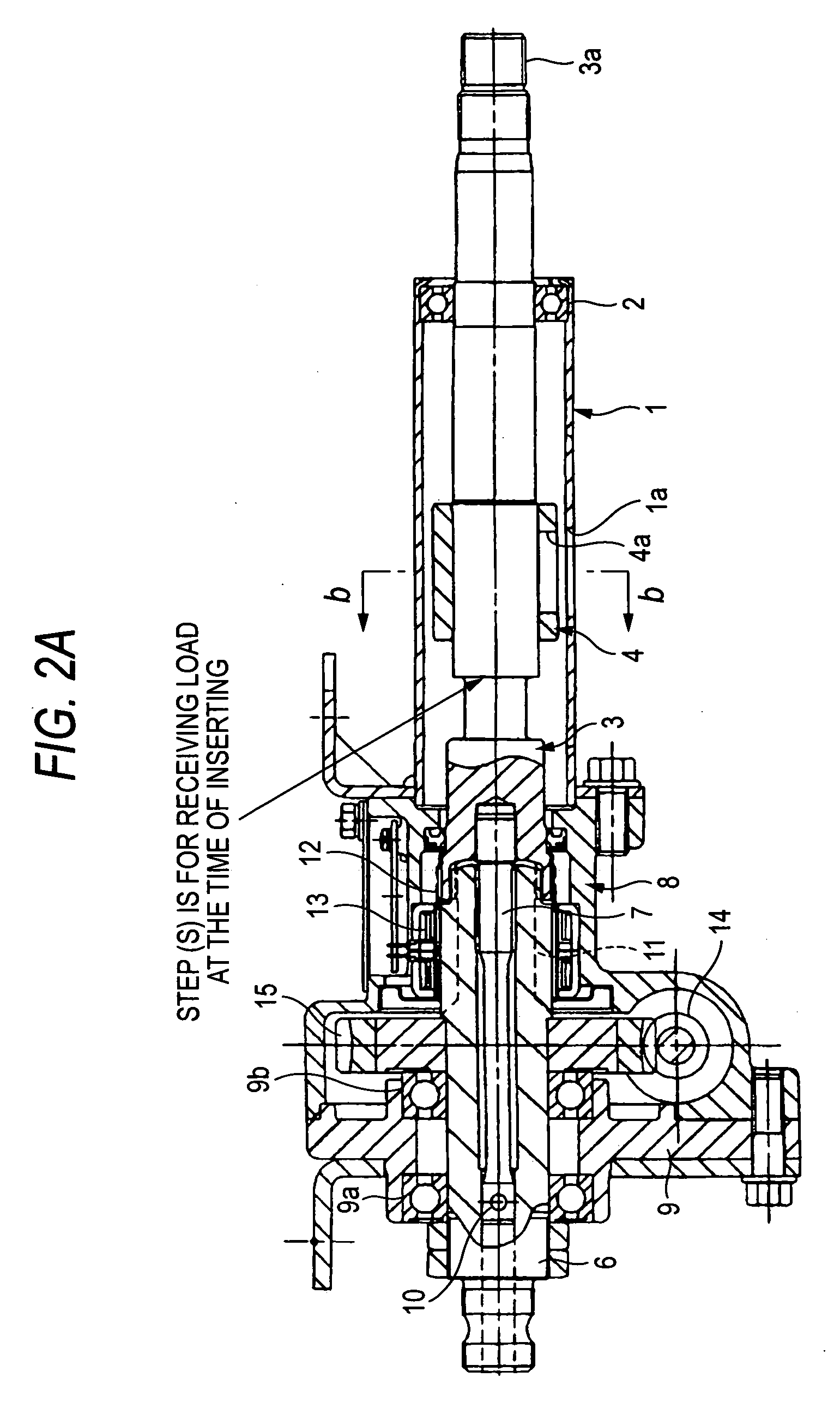
[0242]FIG. 2A is a longitudinal sectional view illustrating an electric power steering system according to a second embodiment of the invention and FIG. 2B is a cross-sectional view taken along Line b-b of FIG. 2A.

[0243] In this embodiment, as can be apparently seen from the figure, the basic structure is similar to that of the first embodiment and thus only differences are described.

[0244] In this embodiment, the key lock collar 4 is directly pressed to the input shaft 3 without using the slip ring.

[0245] As shown in FIG. 2B, in this embodiment, three fitting recesses 3b are formed in the circumferential direction in the steering shaft 3. On the other hand, three fitting protrusions 4b fitted into the fitting recesses 3b at the time of pressing are formed in the circumferential direction in the inner peripheral surface of the key lock collar 4. Accordingly, the pressing force is made insensitive to the cylinder size of the key lock collar 4 and it is difficult to allow the key l...

third embodiment

[0250]FIG. 3 is a longitudinal sectional view illustrating an electric power steering system according to a third embodiment of the invention.

[0251] In this embodiment, as can be apparently seen from the figure, the basic structure is similar to that of the first embodiment and thus only differences are described.

[0252] In this embodiment, the key lock collar 4 is directly pressed to the input shaft 3 without using the slip ring.

[0253] In this embodiment, the input shaft 3 is fitted in advance to the gear housing 8 to form a sub assembly. That is, in the sub assembly, the worm wheel 15 is fitted to the output shaft 6, the torsion bar 7 or the input shaft 3 is coupled thereto, and the steering shaft (the input shaft 3 and the output shaft 6) is inserted to the inside of the sensor coil 13 having a small diameter.

[0254] The key lock collar 4 is fitted directly to the input shaft 3 of the sub assembly, is fixed thereto by welding, and thus the input shaft 3 and the key lock collar ...


PUM


Abstract

A vehicle steering system includes: a sensor mechanism having a sensor coil 13; an antitheft device which has a key lock collar 4 and is disposed on the rear side of the sensor mechanism, in which the outer diameter of the key lock collar 4 of the antitheft device is larger than the inner diameter of the sensor coil 13 of the sensor mechanism; and a member 15 which has a diameter larger than the inner diameter of the sensor coil 13 and which is disposed on the front side of the sensor mechanism, wherein a steering shaft 3 or 6 to which the member 15 having the large diameter is fixed is inserted to the sensor coil 13 and then the key lock collar 4 is fitted to the steering shaft 3 or 6.

Description

TECHNICAL FIELD [0001] The present invention relates to a vehicle steering system such as an electric power steering system including a sensor mechanism and an antitheft device disposed on the rear side thereof and a method of assembling the vehicle steering system. BACKGROUND ART [0002] An electric power steering system for a vehicle is known which steers vehicle wheels by decelerating rotation of an electric motor, which becomes auxiliary steering torque, by the use of a gear to supply the decelerated rotation to an output shaft of a steering mechanism and auxiliary steering force applied to a steering wheel. In such an electric power steering system, the rotation of the electric motor is decelerated using a decelerating mechanism disposed in a housing and is supplied to the output shaft. [0003] In the electric power steering system, an input shaft receiving the steering force from the steering wheel and an output shaft supplying the steering force to the vehicle wheels are connec...

Claims


Application Information

Patent Timeline
Patent Type & Authority Applications(United States)
IPC IPC(8): B62D5/04B60R25/021B62D1/16
CPCB60R25/02105B62D5/04B62D1/16
Inventor KAWAIKE, YUJISANJI, HIROAKINEGISHI, TAKESHI
Owner NSK LTD
Why Eureka
Try Eureka