Clutch

a technology of clutches and components, applied in the field of clutches, can solve the problems of affecting or even damaging the component, unable to prevent the vibration produced or transmitted, and unable to prevent the vibration of the componen

Inactive Publication Date: 2007-10-11
ZF FRIEDRICHSHAFEN AG
View PDF8 Cites 2 Cited by
  • Summary
  • Abstract
  • Description
  • Claims
  • Application Information

AI Technical Summary

Benefits of technology

[0013] In order to maintain the generated coupling effect at times when the clutch is engaged, the electric motor can feature a brake with integrated zero-current operation of the electric motor during such periods. Owing to this design, the electric motor is not constantly powered, which is advantageous for the service life of the electric motor, as well as for the operating costs of the motor vehicle.

Problems solved by technology

However, it has been impossible to prevent the vibrations produced or transmitted by the parts of the clutch attached to the disengaging device from being conducted to the electromagnetic actuator and negatively influencing or even damaging this component.

Method used


Image

  • Clutch
  • Clutch

Examples


Embodiment Construction

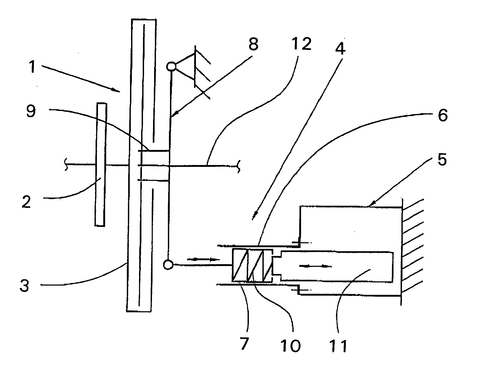
[0017]FIG. 1 shows a clutch 1 in the form of a friction clutch in an engaged position, which is situated in the power train of a motor vehicle between a combustion engine and a transmission. The basic design of such a clutch is well known so that only an explanation of the individual components of the clutch is necessary.

[0018] To begin with, the clutch 1 consists of a clutch housing 3 connected to a fly wheel 2 of the combustion engine, a torque-proof pressure plate, which is capable of axial movement within the clutch housing 3 and a diaphragm spring placed between the clutch housing and the pressure plate. The diaphragm spring comes to bear on both the clutch housing 3 and the pressure plate, the pressure plate being pretensioned in the direction of the fly wheel 2 against a clutch disk with friction lining. This side of the clutch is non-rotatably connected to a transmission input shaft 12.

[0019] A disengaging device 4 is attached to the diaphragm spring, which acts on the rad...


PUM


Abstract

A clutch (1), in particular a friction clutch, with a diaphragm spring exerting stress on a pressure plate of the clutch and connected to a disengaging device (4, 9) that acts on its radial inner area and can be activated by way of an electromechanical actuator (5) and is intended to cancel the stress exerted by the diaphragm spring on the pressure plate when the clutch is engaged. The clutch (1) can be achieved by serially integrating a pressure spring (10) into the mechanical transmission path between the electromechanical actuator that activates the disengaging device and the disengaging device itself so that, when the clutch is in an engaged state, a defined basic force is exerted on the disengaging device while vibration decoupling of the electromechanical actuator is realized.

Description

[0001] This application is a national stage completion of PCT / EP2005 / 003747 filed Apr. 9, 2005, which claims priority from German Application Serial No. 10 2004 019 280.4 filed Apr. 21, 2004.FIELD OF THE INVENTION [0002] The invention relates to a clutch, in particular a friction clutch, which is placed in the power train of a motor vehicle between a combustion engine and a transmission, with a diaphragm spring exerting stress on a pressure plate of the clutch. The diaphragm spring, in turn, is connected to a disengaging device acting on the radial inner area of the diaphragm spring. The disengaging device can in turn be activated by an electromechanical actuator. BACKGROUND OF THE INVENTION [0003] Clutches and clutch actuation devices of this type have been known for a fairly long time in a plethora of embodiments. Their electromechanical actuators feature a pressure spring, which is normally situated parallel to the mechanical transmission path and comes to bear on both the diseng...

Claims


Application Information

Patent Timeline
Patent Type & Authority Applications(United States)
IPC IPC(8): F16D11/00F16D13/50F16D23/12F16D23/14F16D27/00
CPCF16D23/12F16D2023/141F16D28/00
Inventor LUBKE, ECKHARDT
Owner ZF FRIEDRICHSHAFEN AG
Why Eureka
Try Eureka