Method and Device For Comminuting and Sorting Polysilicon

a polysilicon and comminuting technology, applied in the direction of grain treatment, crystal growth process, polycrystalline material growth, etc., can solve problems such as waste, and achieve the effect of increasing yield

Active Publication Date: 2007-10-11
WACKER CHEM GMBH
View PDF11 Cites 88 Cited by
  • Summary
  • Abstract
  • Description
  • Claims
  • Application Information

AI Technical Summary

Benefits of technology

[0006]It is an object of the present invention to provide a device for comminuting and sorting polysilicon, which makes it possible to produce reproducible polysilicon fractions having defined properties with an increased yield, in a single continuous system. These and other objects are achieved by a device comprising a means for feeding a coarse polysilicon fraction into a crushing system, the crushing system associated with a sorting system for classifying a crushed polysilicon fraction, wherein the device is provided with a controller which allows variable adjustment of at least one crushing parameter in the crushing system and / or at least one sorting parameter in the sorting system in response to deviations from a targeted parameter or plurality of parameters. Preferably, the device furthermore comprises a conveyor device from the crushing system to the sorting system.

Problems solved by technology

Thus, isolation of fractions with targeted particle size distributions may entail considerable waste, and adjustment of the crushing to minimize this waste is largely a trial and error process.

Method used


Image

  • Method and Device For Comminuting and Sorting Polysilicon
  • Method and Device For Comminuting and Sorting Polysilicon
  • Method and Device For Comminuting and Sorting Polysilicon

Examples


example 1

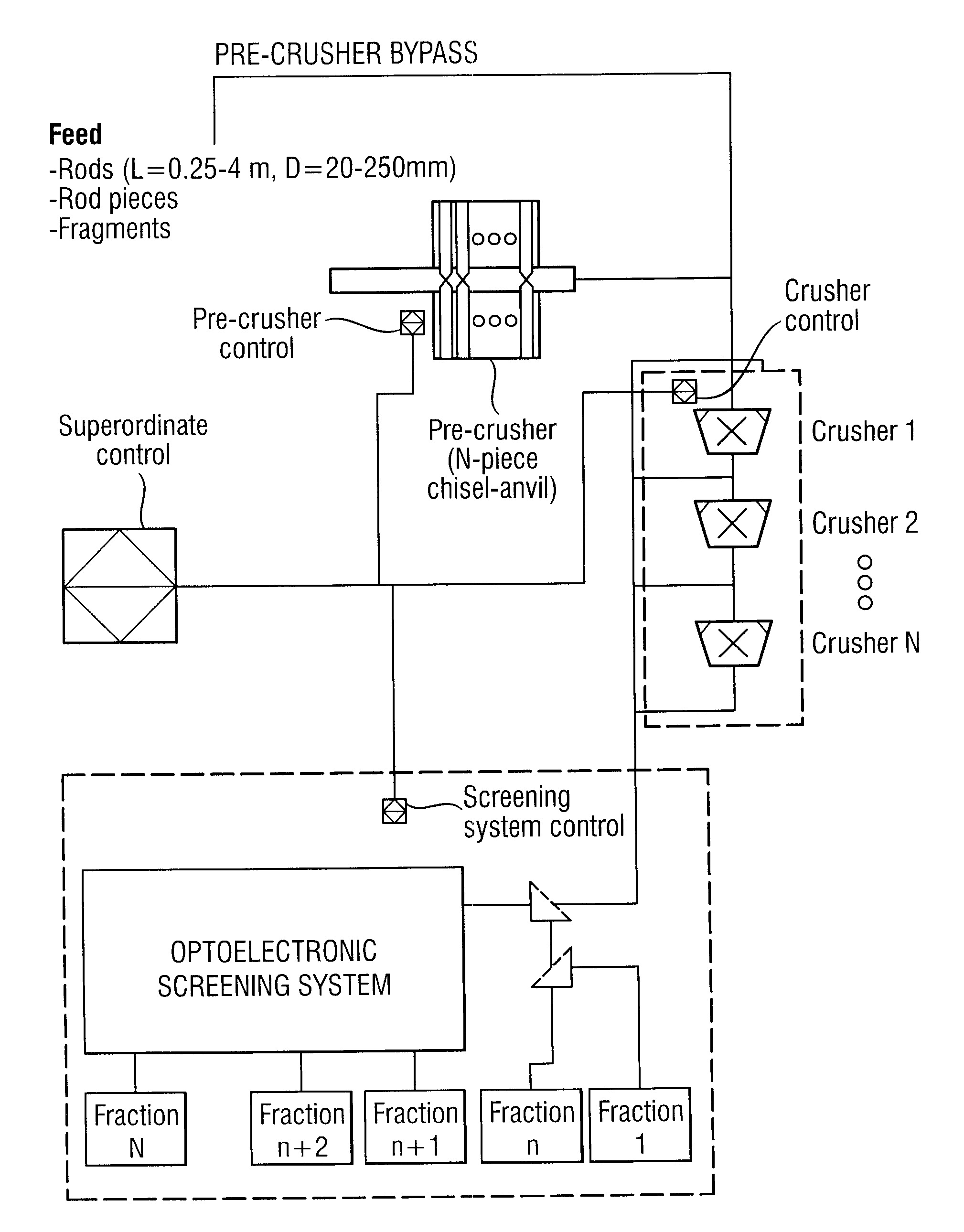
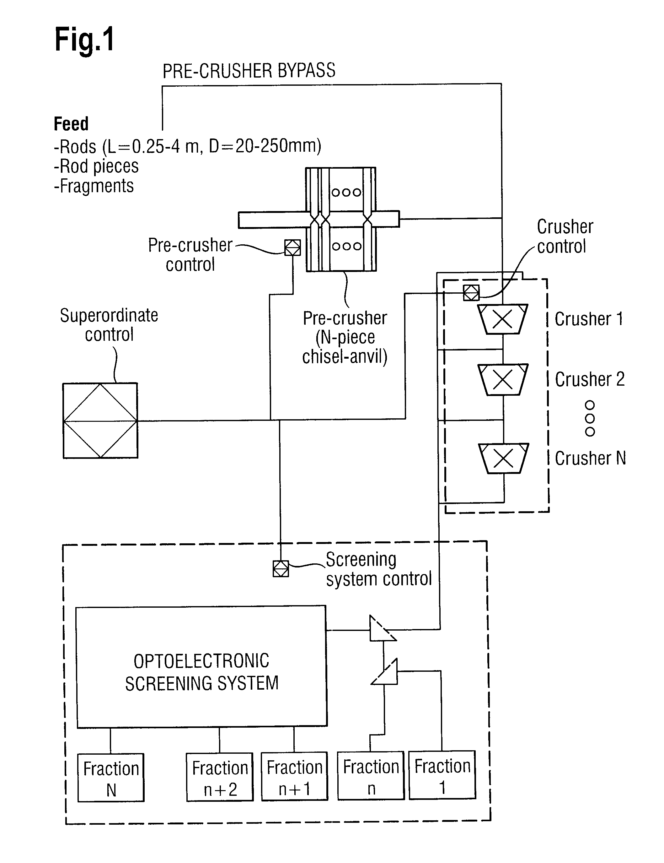
[0061]A polysilicon rod (L=0.25−4 m, D=20−250 mm) is placed on the crushing table of the pre-comminuter. Visual quality control of the rod for foreign bodies, deposits and morphology of the surface is carried out on the crushing table. The rod is placed on a crushing carriage, which conveys the rod automatically into the crushing chamber.

[0062]In a device similar to FIG. 1 of DE 102005019873, an Si rod to be comminuted is put on the bearing prism of the support. The bearing prism is formed by the long sides of two trough shells arranged mutually parallel. The trough shells are installed so that they can be rotated on the crushing carriage.

[0063]A guide rail installed parallel to the crushing carriage makes it easier to fix the Si rod when positioning it. The crushing carriage with the Si rod is subsequently moved into the crushing space, i.e. the region between the chisels. The crushing process is controlled via displacement recording of the carriage, and can be selected variably. A...

example 2

[0065]Instead of the polysilicon rod, individual silicon fragments with a length of more than 25 cm are placed on the crushing table and comminuted as described in Example 1.

example 3

[0066]A coarse polysilicon fraction (from Example 1, 2 or the manual comminution according to the prior art) is sent via a feed device, preferably a funnel, to a roll crusher.

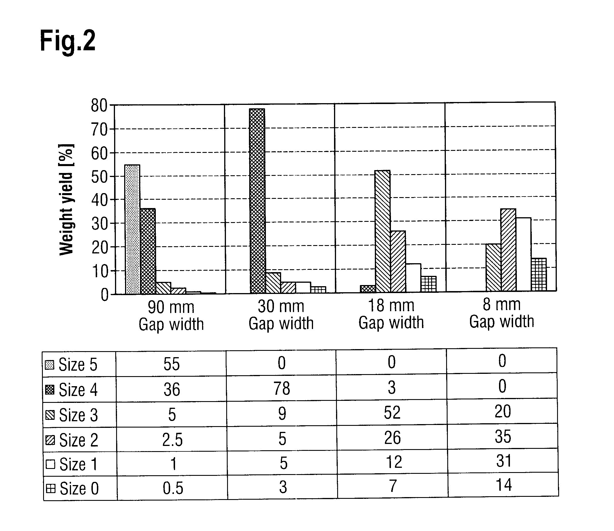
[0067]For the controlled production of fraction 5, the first crushing stage is operated with a circumferential speed of 1 m / sec and a gap spacing (tooth tip to opposite roll bottom) of 90 mm. Other crushing stages are circumvented via a bypass. The crushed material is sent to the sorting system via a conveyor trough (whose conveyor characteristics, for example frequency, are likewise stored in the formula).

[0068]The fine component (fractions 0 and 1) of the material crushed in this way is separated at the mechanical screen with a mesh width of approximately 10 mm, and the separated component is subsequently separated into the fractions 0 and 1 with a further mechanical screening system or a further screen, with an approximately 4 mm mesh width.

[0069]The coarse component (fractions 2, 3, 4 and 5) is sent to the ...


PUM


Abstract

The invention relates to a device for comminuting and sorting polycrystalline silicon, comprising an instrument for feeding a coarse polysilicon fraction into a crushing system, the crushing system associated with a sorting system for classifying the polysilicon fraction, wherein the device is provided with a controller which allows variable adjustment of at least one crushing parameter in the crushing system and / or at least one sorting parameter in the sorting system.

Description

BACKGROUND OF THE INVENTION[0001]1. Field of the Invention[0002]The invention relates to a method and a device for comminuting and sorting highly pure polycrystalline silicon.[0003]2. Background Art[0004]Highly pure polycrystalline silicon, referred to below as polysilicon, is used, inter alia, as a starting material for the production of electronic components and solar cells. It is obtained by thermal decomposition of a gas containing silicon or a gas mixture containing silicon. This process is referred to as chemical vapor deposition (CVD). On a large scale, this process is carried out in so-called Siemens reactors. The polysilicon is thereby created in the form of rods, which are then generally comminuted by means of manual methods. The coarse polysilicon fraction thus obtained has an irreproducible size distribution, with hardly any smaller fraction sizes being created in large quantities. A range of machine-based methods are known, in which a manually pre-comminuted coarse poly...

Claims


Application Information

Patent Timeline
Patent Type & Authority Applications(United States)
IPC IPC(8): B02C25/00
CPCB02C21/00B02C23/08B02C25/00C30B29/06C01B33/02C30B15/00B07C5/08
Inventor SCHAEFER, MARCUSPECH, REINERSCHANTZ, MATTHAEUS
Owner WACKER CHEM GMBH
Why Eureka
Try Eureka