Dark Current Reduction in Back-Illuminated Imaging Sensors and Method of Fabricating Same

a back-illuminated imaging and sensor technology, applied in the direction of semiconductor devices, solid-state devices, radio-controlled devices, etc., can solve the problems of reducing the overall efficiency and sensitivity of the device, adding to the complexity of the fabrication process, and methods that cannot be easily included in conventional semiconductor foundry processing, so as to reduce or eliminate the effect of dark curren

Active Publication Date: 2007-10-11
SRI INTERNATIONAL
View PDF12 Cites 84 Cited by
  • Summary
  • Abstract
  • Description
  • Claims
  • Application Information

AI Technical Summary

Benefits of technology

[0018]FIG. 7 shows a doping profile following the grow of an epitaxial layer using a process which reduces or eliminates dark current, according to another embodiment of the present invention.

Problems solved by technology

It is also desirable to minimize the recombination of the generated carriers before they reach the front side, since such recombination reduces overall efficiency and sensitivity of the device.
This requires additional treatment at the backside of the device, which adds to complexity of the fabrication process.
These methods can not be easily included in conventional semiconductor foundry processing, and require more expensive custom processing.
They are therefore often not cost-effective and not suitable for commercial manufacturing.
Another problem encountered with the design and operation of back-illuminated imagers is the presence of dark current.
Dark current is detrimental to back-illuminated imager operation because excess dark current signal collected along with a desired optically generated signal results in higher levels of fixed pattern and excess random shot noise.
Since dark current noise is uncorrelated with other imager noise sources, the noise due to dark current adds to the overall noise from other sources in quadrature.
Dark current noise increases with increased temperature.

Method used


Image

  • Dark Current Reduction in Back-Illuminated Imaging Sensors and Method of Fabricating Same
  • Dark Current Reduction in Back-Illuminated Imaging Sensors and Method of Fabricating Same
  • Dark Current Reduction in Back-Illuminated Imaging Sensors and Method of Fabricating Same

Examples


Embodiment Construction

[0019] The following embodiments are intended as exemplary, and not limiting. In keeping with common practice, figures are not necessarily drawn to scale.

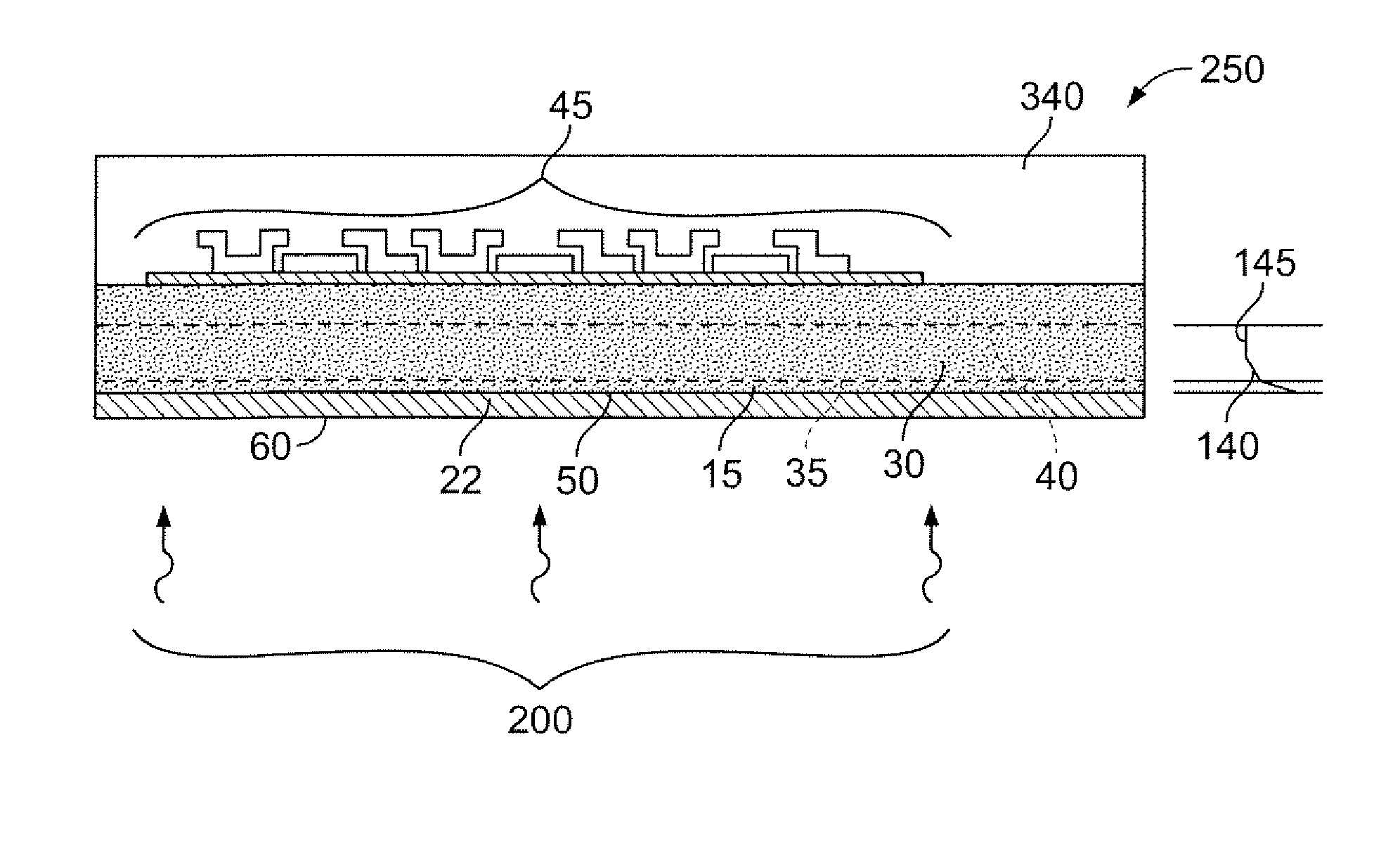
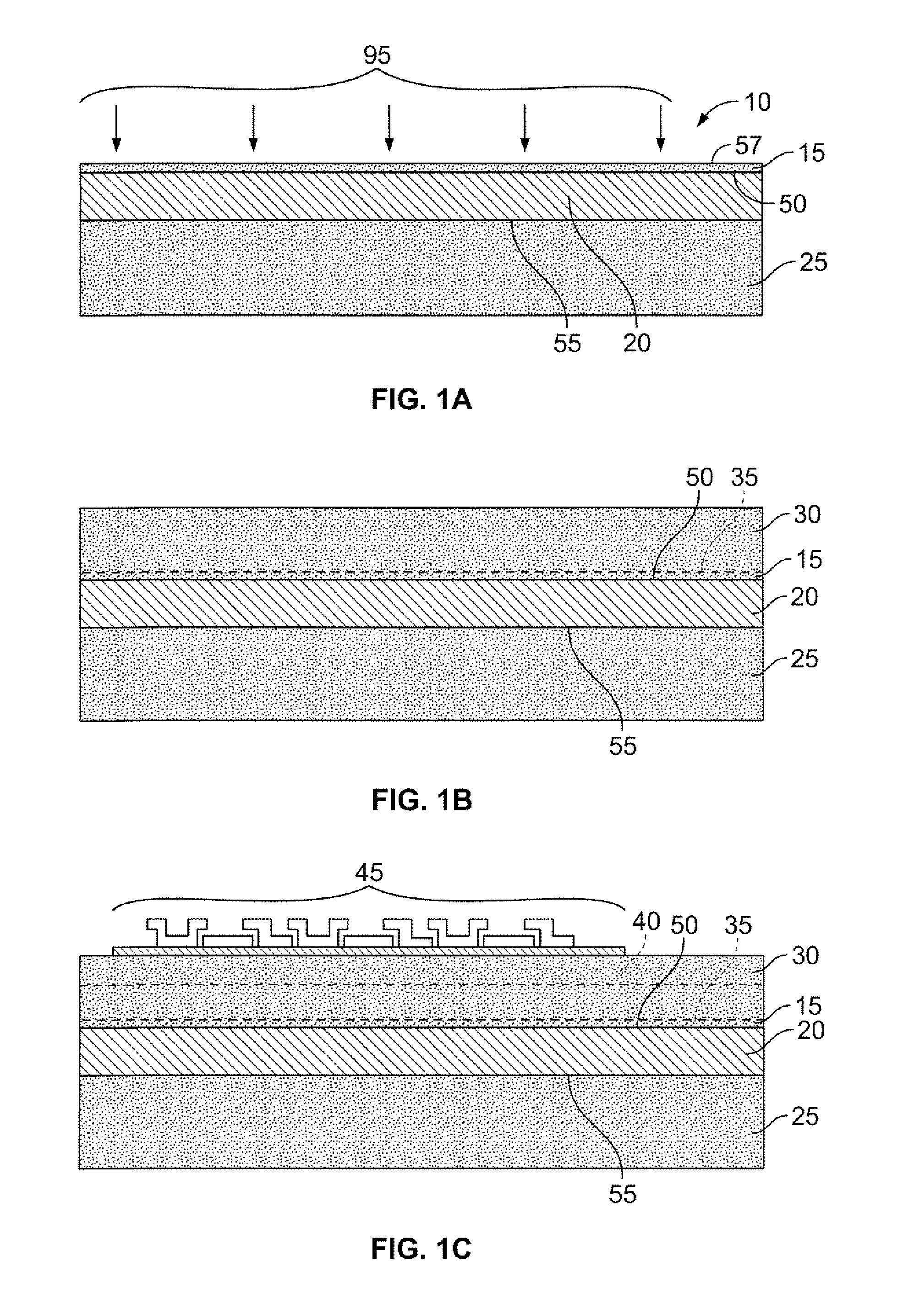
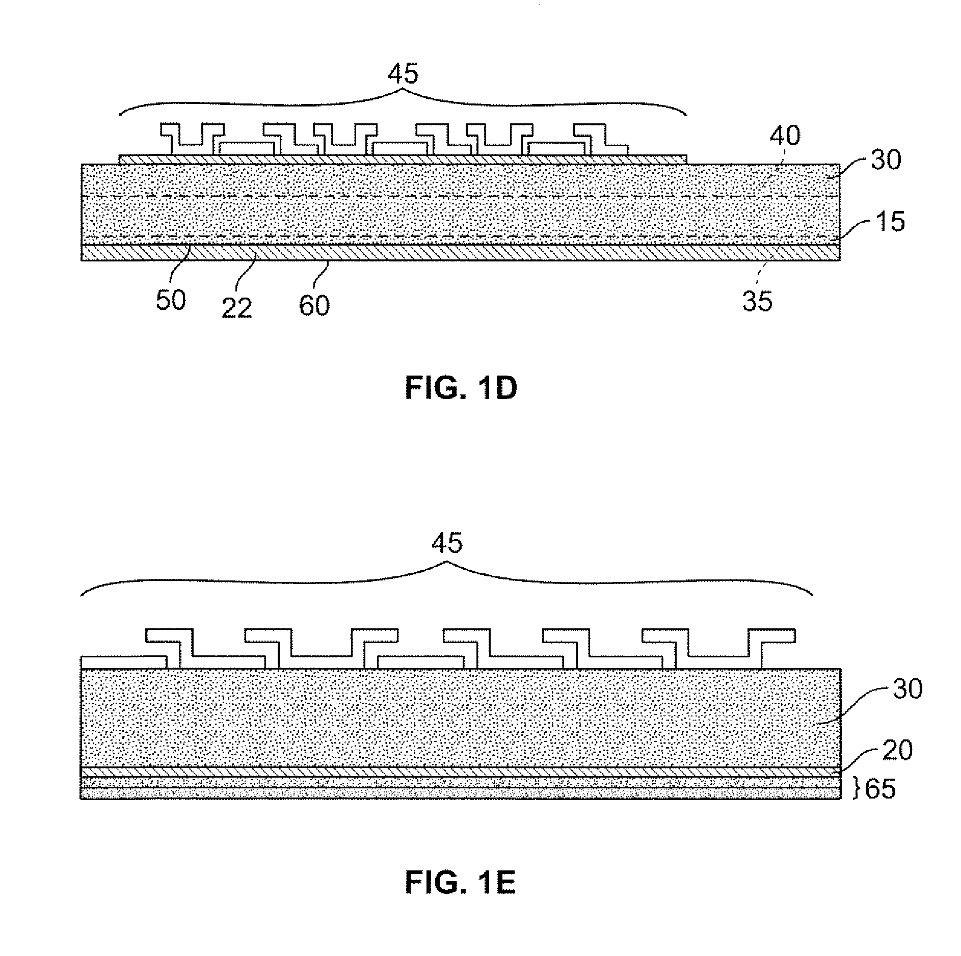
[0020]FIGS. 1A, 1B, 1C, and 1D illustrate an embodiment of a process and a resulting structure. FIG. 1A illustrates initial substrate 10 sometimes referred to in the art as an ultra-thin semiconductor-on-insulator (UTSOI) substrate. FIG. 1B illustrates the state of process embodiment following growth of epitaxial layer 30. FIG. 1C illustrates the state of process embodiment following a step of fabrication of imaging components 45 on and in epitaxial layer 30. As part of this step, one or more electrical junctions, or “pn-junctions”40 are formed in epitaxial layer 30. FIG. 1D illustrates a completed state of the process and the resulting imaging device. FIG. 1E illustrates the state of process embodiment following an optional step of growing one or more anti-reflective coatings. Details of each step follow.

[0021] Starting UTSOI su...


PUM


Abstract

A method for fabricating a back-illuminated semiconductor imaging device on a semiconductor-on-insulator substrate, and resulting imaging device is disclosed. The device includes an insulator layer; a semiconductor substrate, having an interface with the insulator layer; an epitaxial layer grown on the semiconductor substrate by epitaxial growth; and one or more imaging components in the epitaxial layer in proximity to a face of the epitaxial layer, the face being opposite the interface of the semiconductor substrate and the insulator layer, the imaging components comprising junctions within the epitaxial layer; wherein the semiconductor substrate and the epitaxial layer exhibit a net doping concentration having a maximum value at a predetermined distance from the interface of the insulating layer and the semiconductor substrate and which decreases monotonically on both sides of the profile from the maximum value within a portion of the semiconductor substrate and the epitaxial layer. The doping profile between the interface with the insulation layer and the peak of the doping profile functions as a “dead band” to prevent dark current carriers from penetrating to the front side of the device.

Description

CROSS-REFERENCE TO RELATED APPLICATIONS [0001] This application is a continuation-in-part of U.S. patent application Ser. No. 11 / 350,546, filed on Feb. 9, 2006, which in turn claims the benefit of U.S. Provisional Application No. 60 / 652,409 filed on Feb. 11, 2005. The entire disclosures of U.S. patent application Ser. No. 11 / 350,546 and U.S. Provisional Application No. 60 / 652,409 are hereby incorporated by reference herein.FIELD OF THE INVENTION [0002] The field of invention is semiconductor device fabrication and device structure. More specifically, the field is fabrication and structure of back-illuminated semiconductor imaging devices, with emphasis on the reduction of dark current. BACKGROUND OF THE INVENTION [0003] Thinned, back illuminated, semiconductor imaging devices are advantageous over front-illuminated imagers for high fill factor and better overall efficiency of charge carrier generation and collection. A desire for such devices is that the charge carriers generated by...

Claims


Application Information

Patent Timeline
Patent Type & Authority Applications(United States)
IPC IPC(8): H01L31/0232H01L31/18
CPCH01L27/14643H01L27/148H01L27/1464H01L31/1892Y02E10/50H01L31/18H01L27/14
Inventor LEVINE, PETER ALANSWAIN, PRADYUMNABHASKARAN, MAHALINGAM
Owner SRI INTERNATIONAL
Why Eureka
Try Eureka