
Specific absorption rate measuring system, and a method thereof

a measuring system and absorption rate technology, applied in the field of biological tissue equivalents, can solve the problems of phantom solvent agitation, long measurement time, noise generation, etc., and achieve the effects of accurate measurement, reduced interference of interface reflection on the electromagnetic field near the electro-optical crystal, and reduced disturbance of the electric field in the electro-optical crystal by interface reflection

Inactive Publication Date: 2007-10-11
NTT DOCOMO INC +1
View PDF2 Cites 10 Cited by
  • Summary
  • Abstract
  • Description
  • Claims
  • Application Information

AI Technical Summary

Benefits of technology

[0054] As described above, according to the present invention, since the electric-field detecting element is constituted by nonmetallic materials, it is possible to measure the SAR distribution without the disturbance that is generated in the case of the conventional technology. Further, since the electro-optical crystals having a dielectric constant approximately equal to that of the phantom are used as a sensor head, reflection due to difference of the dielectric constants is reduced, and the SAR distribution can be more accurately measured. Furthermore, since spatial resolution of the measurement is proportional to a diameter of a beam of the light that penetrates the electro-optical crystal, the spatial resolution can be raised, theoretically, to as small as the wavelength of the light (several μm). Furthermore, since a change in a refractive index of the electro-optical crystal at the measuring point depends on deviation of a dipole that follows the electromagnetic wave, the SAR measurement is available in a wide band range, from the MHz band to the THz band.
[0055] According to the present invention, disturbance of the electric field in the electro- optical crystal by interface reflection is reduced, and the influence of the interface reflection on the electromagnetic field near the electro-optical crystals is reduced by using the electro-optical crystal that has a dielectric constant approximately equal to that of the phantom. Therefore, the specific absorption rate measuring system capable of obtaining an accurate SAR distribution is realized.

Problems solved by technology

This is a problem of the electric-field measuring method.
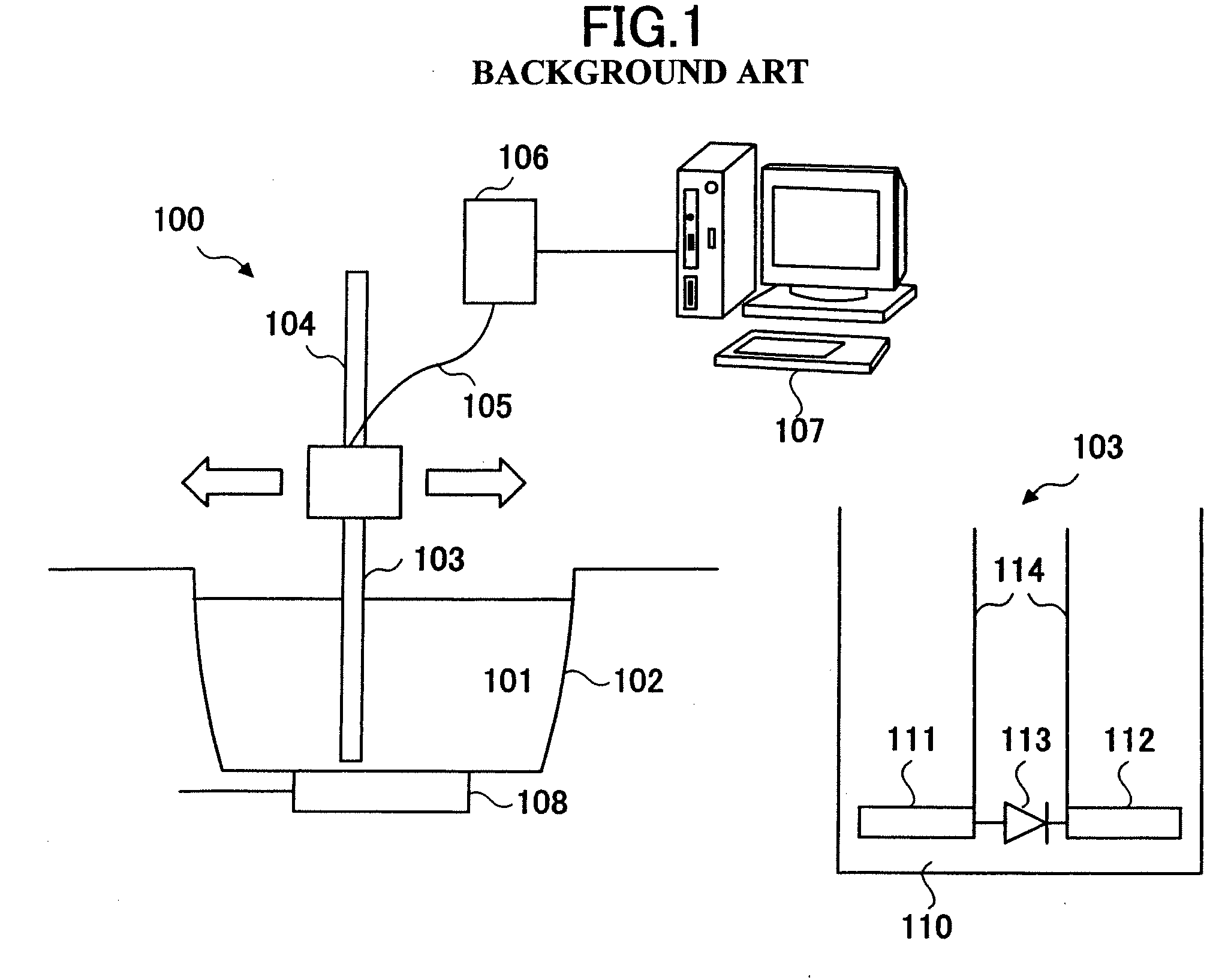
Further, since the probe for detecting the electric field, or a 3-dimensional electric-field sensor, is moved in the liquid phantom for measuring SAR, the liquid (a phantom solvent) is agitated, and noise is generated by vibration of the probe or sensor.
If a time until the solvent settles into a steady state is waited for in order to avoid the noise, measurement will take a long time.
If two or more electric-field sensors are arranged in two dimensions or three dimensions in the phantom in order to shorten the measuring time, the aggregate of the sensors (short dipoles) will behave as a conductor, and will generate a great disturbance to the electromagnetic field to be measured.
Consequently, a SAR distribution that is different from actual may be measured, which is a problem.

Method used


Image

  • Specific absorption rate measuring system, and a method thereof
  • Specific absorption rate measuring system, and a method thereof
  • Specific absorption rate measuring system, and a method thereof

Examples


Embodiment Construction

[0062] In the following, embodiments of the present invention are described with reference to the accompanying drawings, wherein common reference numbers are assigned to items that have the same functions, and the descriptions are not repeated.

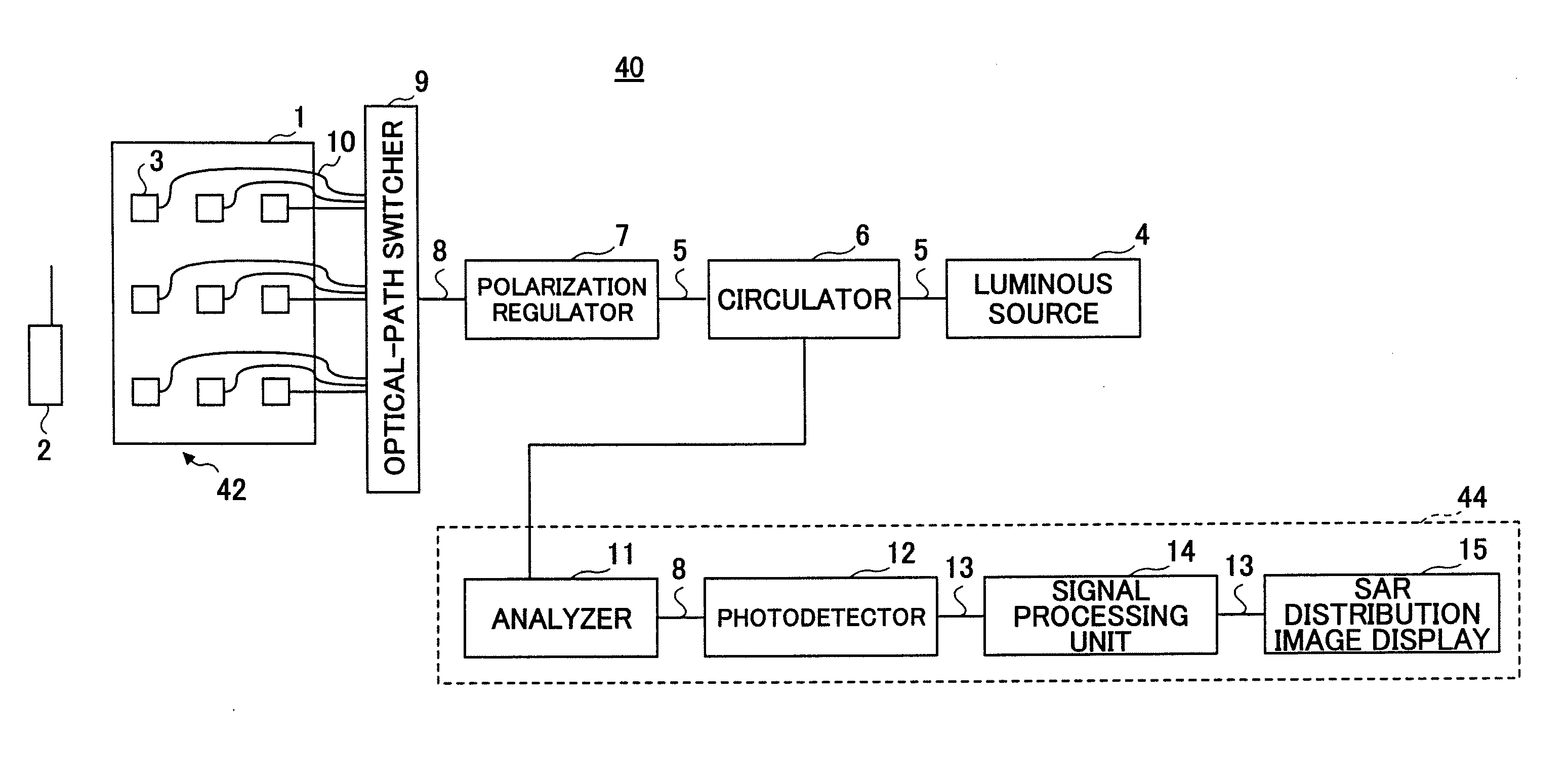
[0063]FIG. 4 is a block diagram of a specific absorption ratio measuring system 40 according to the embodiment of the present invention. The specific absorption rate measuring system 40 includes a biological tissue equivalent phantom unit 42 that is constituted by a simulated human body (phantom) 1 consisting of liquid, gel, a solid-state object, etc., for simulating the electric constant of the human body, electro-optical crystals 3 that have a dielectric constant approximately equal to that of the phantom 1, and bare fibers 10.

[0064] The specific absorption rate measuring system 40 further includes

[0065] an electromagnetic wave generator 2 such as a cellular phone,

[0066] a linearly polarized luminous source 4 such as DFB-LD,

[0067] a pol...


PUM


Abstract

A biological tissue equivalent phantom unit to be used by the specific absorption rate measuring system for evaluating absorption of electromagnetic wave energy includes a biological tissue equivalent phantom for absorbing an electromagnetic wave. In addition, two or more electro-optical crystals are arranged at two or more measurement points in the biological tissue equivalent phantom. The electro-optical crystals have a dielectric constant that is approximately equal to that of the biological tissue equivalent phantom. Two or more optical fibers are laid in the biological tissue equivalent phantom for optically connecting each of the electro-optical crystals to an external destination.

Description

CROSS-REFERENCE TO RELATED APPLICATIONS [0001] This application is a Continuation of U.S. patent application Ser. No. 11 / 263,946, filed Nov. 2, 2005, and claims priority to Japanese Patent Application No. 2004-319387, filed Nov. 2, 2004, the entire contents of these applications are incorporated herein by reference.BACKGROUND OF THE INVENTION [0002] 1. Field of the Invention [0003] The present invention relates to a biological tissue equivalent phantom unit (phantom unit) used by a specific absorption rate measuring system for evaluating absorption of electromagnetic wave energy; a specific absorption rate measuring system using the phantom unit; and a method thereof. [0004] 2. Description of the Related Art [0005] In recent years and continuing, requirements are increasing for quantitatively evaluating a thermal effect caused by an electromagnetic wave emitted by a wireless radio transmitter; and a system that is capable of accurately and swiftly measuring a specific absorption rat...

Claims


Application Information

Patent Timeline
Patent Type & Authority Applications(United States)
IPC IPC(8): G01R27/04G01R29/08
CPCG01R29/0885G01N21/55G01R29/08
Inventor ONISHI, TERUOYAMAGUCHI, RYOUEBAYASHI, SHINJINAGATSUMA, TADAOSHIMIZU, NAOFUMITOGO, HIROYOSHI
Owner NTT DOCOMO INC
Learn More