Driver circuit, display apparatus, and method of driving the same

a technology of display apparatus and drive circuit, which is applied in the direction of instruments, static indicating devices, etc., can solve the problems of increased power consumption, color unevenness in a displayed image, and the inability to achieve the required luminance in some cases, so as to reduce the voltage of the data line to be driven

Inactive Publication Date: 2007-10-11
RENESAS ELECTRONICS CORP
View PDF6 Cites 14 Cited by
  • Summary
  • Abstract
  • Description
  • Claims
  • Application Information

AI Technical Summary

Benefits of technology

[0011]In the invention, by precharging at least a data line adjacent to a data line to be driven to a precharge voltage adequate for the adjacent data line, change in the voltage of the data line to be driven is reduced. This decreases the influence of the adjacent data line on the voltage.

Problems solved by technology

However, when driven on a time division basis, if a data line R is selected and a display signal with negative polarity is written, charge / discharge to parasitic capacitance between pixel electrodes would occur because an adjacent pixel electrode remains positive, leading to increased power consumption.
Besides, the required luminance could not be attained in some cases.
This would affect the voltage of an adjacent data line, resulting in color unevenness in a displayed image.
As the data lines are longer, the parasitic capacitance is larger and the influence of parasitic capacitance becomes larger, leading to more serious display color fluctuation.
This is because the switch on the panel for a driven pixel is not turned OFF and thus the data line is more susceptible to the influence of charge switching for other data lines.

Method used


Image

  • Driver circuit, display apparatus, and method of driving the same
  • Driver circuit, display apparatus, and method of driving the same
  • Driver circuit, display apparatus, and method of driving the same

Examples


first embodiment

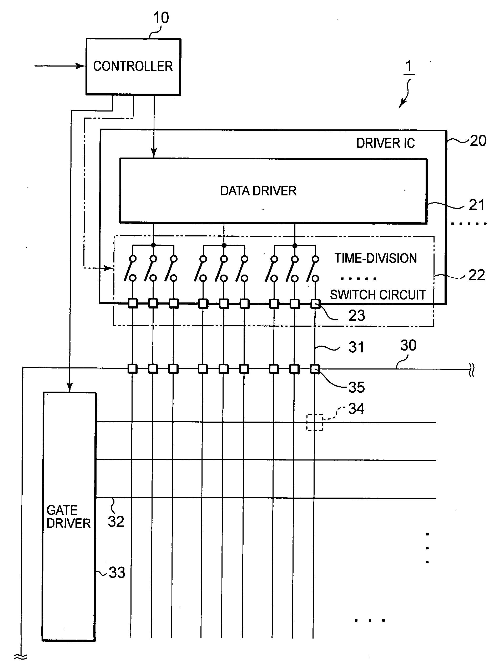
[0021]FIG. 1 shows a display apparatus according to the first embodiment of the invention. As illustrated in FIG. 1, a liquid crystal display apparatus 1 based on an RGB time division driving method according to this embodiment includes: an active matrix liquid crystal display panel 30; a gate driver 33 for driving scanning lines; a driver IC 20 including a data driver (source driver) 21 for driving data lines; a controller 10 for supplying display data and various timing signals; and a power supply circuit (not shown). The gate driver may be located outside the display panel or the driver IC including the data driver may be located on the panel.

[0022]The liquid crystal display panel 30 includes: a TFT array substrate where plural scanning lines (gate lines) 32 and plural data lines 31 are arranged in a lattice pattern, pixel electrodes 34 are arranged in a matrix pattern, and TFTs (not shown) as switching elements are connected with the source (data) lines 31 and pixel electrodes; ...

second embodiment

[0057]Next, a second embodiment of the present invention will be described. FIG. 6 is a drive timing diagram according to this embodiment. In the first embodiment, all the data lines are precharged before being actually driven. However, a similar effect may be achieved by precharging and driving some of the data lines simultaneously.

[0058]In the case as shown in FIG. 6, data line Snc is precharged and driven simultaneously. This saves a single switch action, permitting higher driving efficiency.

[0059]As illustrated in FIG. 6, in a horizontal period H, switches GSWna, GSWnb, and GSWnc on the panel are all ON. Then, in period ta, switch SWna turns ON. Consequently precharge voltage Vna which is the same as the drive voltage is supplied to data line Sna and voltage VSna of data line Sna is precharge voltage (=drive voltage) Vna. In the next period tb, switch SWnb turns ON. Consequently precharge voltage Vnb which is the same as the drive voltage is supplied to data line Snb and voltage...


PUM


Abstract

A display apparatus drives a data line on a time division basis. In this process, the data line is driven twice, namely in two modes: a precharge mode and a drive mode. Before the drive mode in which a drive voltage according to display data is supplied to a data line among a set of data lines to be driven on a time division basis, a precharge voltage is supplied at least to a data line adjacent to the data line individually.

Description

FIELD OF THE INVENTION[0001]The present invention relates to a driver circuit which drives a data line in a display apparatus on a time division basis and a display apparatus with a time division driver circuit and a method of driving the same.BACKGROUND OF THE INVENTION[0002]In the field of active-matrix liquid crystal display apparatuses, the precharge technique which speeds up liquid crystal driving has been known. In this precharge technique, prior to driving a data line according to display data, the data line is precharged to a given voltage to reduce the charge / discharge of the data line in supplying a drive voltage according to display data (for example, see Laid Open Japanese Application JP 2005-37832A and JP 2005-115342A).[0003]On the other hand, the electronic field-effect mobility of poly-Si is approx. several dozen to 200 cm2 / Vs, which is higher than that of amorphous Si (approx. 0.5 to 1 cm2 / Vs). For this reason, the use of poly-Si TFTs on a substrate on which a liquid...

Claims


Application Information

Patent Timeline
Patent Type & Authority Applications(United States)
IPC IPC(8): G09G3/36
CPCG09G3/3688G09G2300/0408G09G2320/0209G09G2310/0297G09G2310/0248
Inventor MIYAZAKI, KIYOSHIOOTANI, KEIGONAGATO, HIDEKAZU
Owner RENESAS ELECTRONICS CORP
Why Eureka
Try Eureka