Optical Guide and Online Control of a Tool

a tool and optical guide technology, applied in the direction of mechanical control devices, color television, television systems, etc., can solve the problems of requiring a large amount of space transverse to the movement direction, and requiring a large amount of spa

Inactive Publication Date: 2007-10-11
TROPF ING HERMANN
View PDF9 Cites 16 Cited by
  • Summary
  • Abstract
  • Description
  • Claims
  • Application Information

AI Technical Summary

Benefits of technology

[0013] It would also be advantageous to provide a system and method that avoid the above described disadvantages associated in the current state of the art.
[0014] According to an embodiment, there is disclosed an arrangement for optical control of a work result of a tool. According to an aspect, the system is directed to a camera coupled to an optics system and having an imaging beam path for optically guiding a tool, wherein the tool is moved relative to a workpiece. In an aspect, the tool is moved along a straight path, Alternatively, the tool may be moved along a curved path. The tool is positioned in an image field of the camera such that a tool support in the imaging beam path is at least one of approximately centrically located in the imaging beam path and located directly in a pupil of the optics or in an optical vicinity thereof such that the tool support is either not seen or is sufficiently blurred, further wherein a working area around the workpiece is visible for analysis.
[0015] According to another embodiment, a method is disclosed for joining or gripping by a technique of visual servoing, comprising providing a tool; providing a camera coupled to an optics system and a control system for guiding the tool via the camera and the optics system, and having an imaging beam path, wherein the tool is moved relative to a workpiece along a straight or a curved path, for example; providing a tool support coupled to the tool; positioning the tool in an image field of the camera such that the tool support is either centrically located in the imaging beam path or located directly in a pupil of the optics or in an optical vicinity thereof, such that the tool support is not seen or is sufficiently blurred, further such that a working area around the workpiece is visible for analysis.

Problems solved by technology

However, in the case of large parts as they are common in car manufacturing, a lot of space may be required.
In all cases, at least two cameras, and often, preferably, three are required to create a monitoring area around the workpiece A disadvantage of these arrangements is that several cameras are generally necessary whose pictures even have to be analysed at the same time.
Furthermore, a greater amount of space is required transverse to the movement direction.
This is particularly disadvantageous when the bead is to be applied under cramped space conditions (e.g., along steep profiles).
Other disadvantages include disturbances in illumination due to shadowing.
Moreover, these arrangements may not be suitable for a height controller only with several or more cameras.
When the tool is guided by an optical sensor, e.g., when tracking an edge, a groove, a weld bead, or when selectively setting the movement by means of “landmarks” such as holes or edges, the same problems and disadvantages may be present: according to the prior art so far.

Method used


Image

  • Optical Guide and Online Control of a Tool
  • Optical Guide and Online Control of a Tool
  • Optical Guide and Online Control of a Tool

Examples


Embodiment Construction

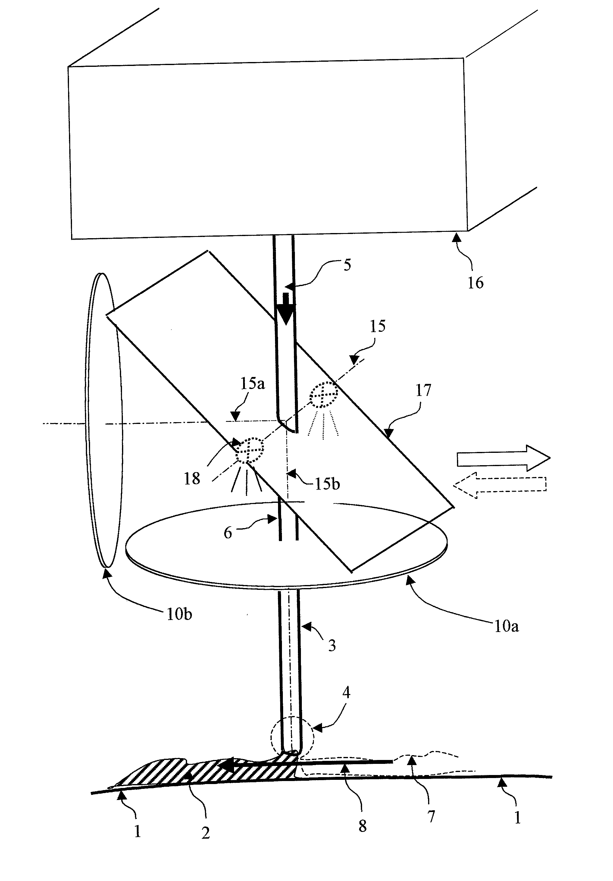
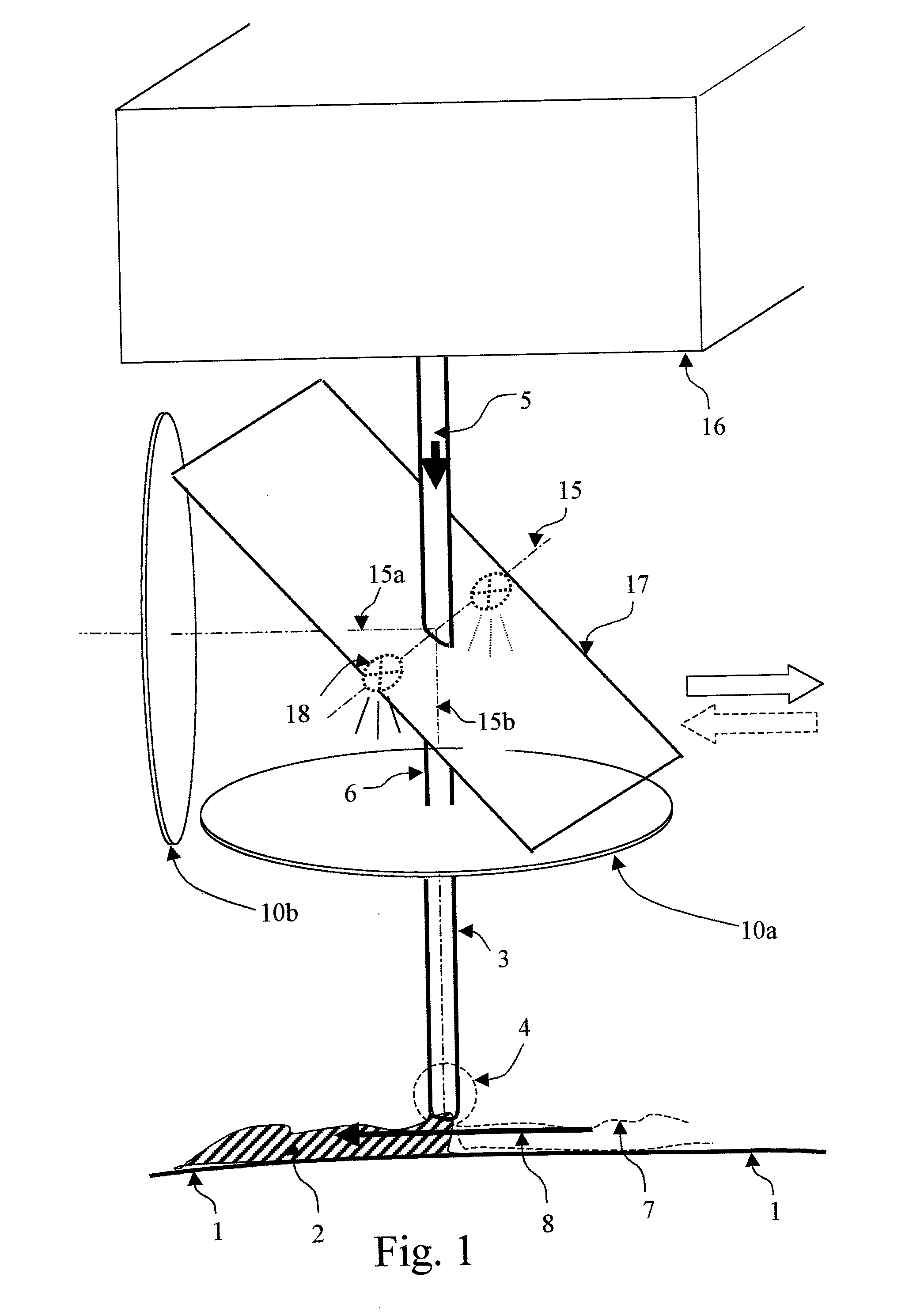
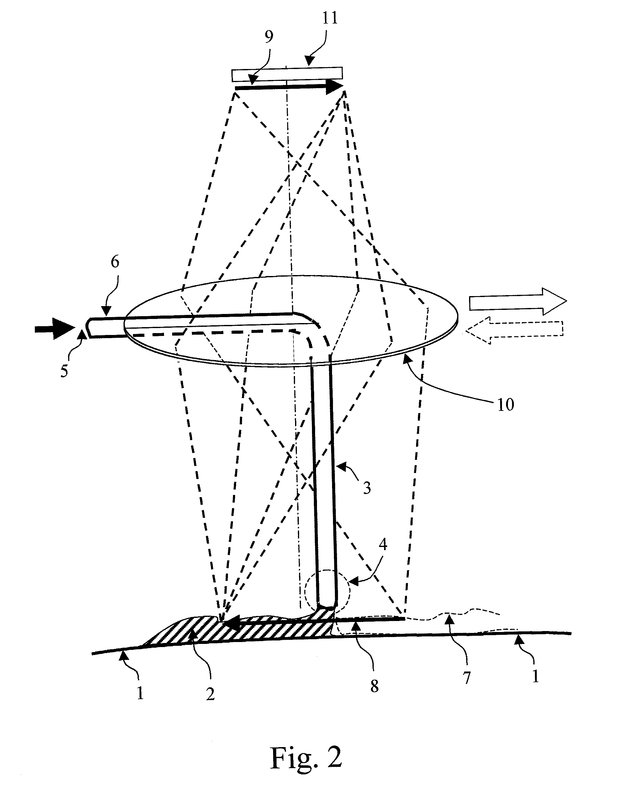
[0023] Referring to the various figures, and, in particular to FIG. 2, for optical control of the work result of a tool 3 and / or for optically guiding the tool 3 via a camera 11 with optics 10, 10a, 10b, wherein the tool is moved relative to a workpiece 1, in particular on a curved path, the tool is placed at least approximately centrically in the image field 8, and its support 6 be located within the beam path either approximately centrically in the beam path, directly in a pupil 15 (FIG. 1) of the optics 10, 10a, 10b, or at least near enough to the pupil of the optics that the support 6 is not visible, or is blurred, such that the working area (image field) 8 around the workpiece is visible for analysis.

[0024] The pupil is the aperture (e.g., aperture stop) of an optical system. In the case of very simple lens systems, the lens itself is the pupil. In more complex systems, e.g., in the known Köhler illumination, the aperture is depicted in real intermediate images. The term pupil...


PUM

PropertyMeasurementUnit
semi-transparentaaaaaaaaaa
viscousaaaaaaaaaa
widthaaaaaaaaaa

Abstract

Embodiments of the invention are directed to a system arrangement and method for the optical control of the work result of a tool and/or guiding the tool with all-around view, wherein tool and workpiece are moved relative to each other, along a straight path or, particularly, on curved path. According to an aspect, the tool is positioned centrically in the image field and a tool support is located centrically in the beam path or in a pupil of the optics, or in an optical vicinity of the pupil. An arrangement for 3D analysis is also indicated. Advantageously, only one camera need be used, providing a lean design of viewing and illumination, and usable under cramped space conditions. Guiding, processing and control are possible in a single operation using a single camera. Methods for, e.g., applying viscous masses, welding, deburring, and related applications are also disclosed.

Description

RELATED APPLICATION DATA [0001] This application claims priority under 35 USC§119(a-d) to DE 10 2006 006 204.3-14 filed in the German Patent Office on Feb. 9, 2006, the subject matter of which is hereby incorporated by reference in its entirety. BACKGROUND [0002] 1. Field of the Invention [0003] Embodiments of the invention generally relate to tool control apparatus and methods. More specifically, the disclosed embodiments are directed to methods and apparatus for optically guiding a tool and / or the control of the work result of a tool that is moved relative to a workpiece in a straight or a curved path, for example. Non limiting example applications of the disclosed embodiments include the application of highly viscous masses such as adhesive beads or sealing beads, welding, soldering, marking, deburring, engraving. [0004] 2. Description of Related Art [0005] The business and technology related to the application of highly viscous masses such as adhesive beads or sealing beads, wel...

Claims


Application Information

Patent Timeline
Patent Type & Authority Applications(United States)
IPC IPC(8): H04N7/18G06F19/00
CPCB23K9/0956
Inventor TROPF, ING. HERMANN
Owner TROPF ING HERMANN
Why Eureka
Try Eureka