Image encoding apparatus and image decoding apparatus

a technology of image encoding and decoding apparatus, which is applied in the direction of geometric image transformation, instruments, computing, etc., can solve the problems of high cost, low picture quality, and increase the cost, and achieve the effect of large storage capacity, large image rotation/inverting process, and no tile distortion

Inactive Publication Date: 2007-10-11
MEGACHIPS
View PDF3 Cites 36 Cited by
  • Summary
  • Abstract
  • Description
  • Claims
  • Application Information

AI Technical Summary

Benefits of technology

[0011]Without using a memory having a large storage capacity and without causing tile distortion, the image rotating process can be executed efficiently.
[0013]Without using a memory having a large storage capacity and without causing tile distortion, the image inverting process can be executed efficiently.
[0016]Without using a memory having a large storage capacity and without causing tile distortion, the image rotating process can be executed efficiently.
[0018]Without using a memory having a large storage capacity and without causing tile distortion, the image inverting process can be executed efficiently.
[0019]An object of the present invention is to provide an image encoding apparatus and an image decoding apparatus realizing efficient image rotating / inverting process without using a memory having a large storage capacity and without causing tile distortion.

Problems solved by technology

However, the methods have to use an expensive page memory, the cost is high.
Moreover, to store a whole image, a memory having a large storage capacity has to be mounted, and it increases the cost.
However, rectangular distortion called tile distortion occurs due to the tiling process and the picture quality is low.

Method used


Image

  • Image encoding apparatus and image decoding apparatus
  • Image encoding apparatus and image decoding apparatus
  • Image encoding apparatus and image decoding apparatus

Examples


first embodiment

Outline of General Apparatus

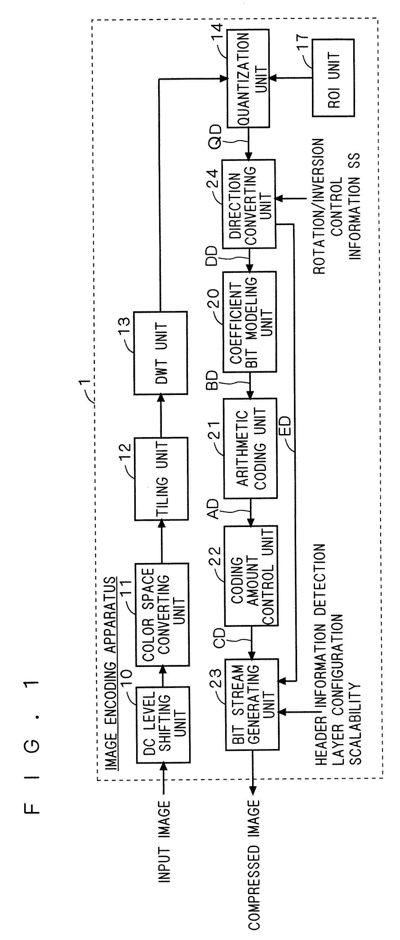
[0047]FIG. 1 is a functional block diagram showing the configuration of an image encoding apparatus 1 on the basis of the JPEG 2000 compression, according to a first embodiment of the present invention. As shown in FIG. 1, the image encoding apparatus 1 has a DC level shifting unit 10, a color space converting unit 11, a tiling unit 12, a DWT unit 13, a quantization unit 14, an ROI unit 17, a direction converting unit 24, a coefficient bit modeling unit 20, an arithmetic coding unit 21, a coding amount control unit 22, and a bit stream generating unit 23.

[0048]All or part of the processing units 10 to 14, 17, and 20 to 23 constructing the image encoding apparatus 1 may be constructed as hardware or a program for making a microprocessor function.

[0049]The DC level shifting unit 10 performs a DC level shifting process as necessary on an image signal (an input image in FIG. 1) supplied to the image encoding apparatus 1 from the outside.

[0050]The color space ...

second embodiment

[0129]Although the image encoding apparatus for coding an input image signal and outputting a compressed image has been described in the foregoing first embodiment, in a second embodiment, an image decoding apparatus for decoding an input compressed image and outputting an image signal will be described. The points different from the first embodiment will be mainly described below.

Outline of Apparatus

[0130]FIG. 21 is a functional block diagram showing the configuration of an image decoding apparatus 400 on the basis of JPEG 2000 compression, according to a second embodiment of the present invention. As shown in FIG. 21, the image decoding apparatus 400 has a DC level shifting unit 410, a color space converting unit 411, a tiling unit 412, an inverse DWT unit 413, an inverse quantization unit 414, a direction converting unit 424, a coefficient bit modeling unit 420, an arithmetic decoding unit 421, and a bit stream analyzing unit 423.

[0131]All or part of the processing units 410 to 4...


PUM


Abstract

A conversion control unit divides a transform coefficient into code blocks. A storing device has a storage capacity corresponding to data size of the code blocks. To the conversion control unit, rotation / inversion control information including information of the rotation angle and the inverting direction is input. The conversion control unit generates a control signal on the basis of the rotation / inversion control information and sub-band information of the transform coefficient. An address generating unit generates a write address on the basis of a control signal. By accessing the storing device in predetermined order on the basis of the write address at the time of writing the code block to the storing device, an image rotating / inverting process is performed.

Description

BACKGROUND OF THE INVENTION[0001]1. Field of the Invention[0002]The present invention relates to an image encoding apparatus and an image decoding apparatus.[0003]2. Description of the Background Art[0004]Hitherto, as methods of obtaining a rotated image or inverted image subjected to compression coding, a method of rotating / inverting a whole image and, after that, performing compression coding on the image and a method of performing compression coding on an image and then rotating / inverting the whole image are known. A technique of dividing an image into a plurality of small regions (tiles) by tiling process and performing a rotating process on a tile unit basis is also conventionally known.[0005]In an input device such as CCD and a display device such as LCD, image data is processed in a raster scan order. Therefore, it is desired that image data be stored in the raster scan order in a memory.[0006]In the method of rotating / inverting a whole image and performing compression coding...

Claims


Application Information

Patent Timeline
Patent Type & Authority Applications(United States)
IPC IPC(8): G06K9/46G06T3/60H03M7/30H04N1/387H04N1/41H04N19/134H04N19/34H04N19/423H04N19/60H04N19/63H04N19/80H04N19/91
CPCH04N13/0454H04N19/647H04N19/423H04N19/129H04N19/645H04N19/63H04N13/359
Inventor MIZUNO, YUSUKE
Owner MEGACHIPS
Why Eureka
Try Eureka