Particle patterning chip
- Summary
- Abstract
- Description
- Claims
- Application Information
AI Technical Summary
Problems solved by technology
Method used
Image


Examples
example 1
An Embodiment of a Cell Patterning Device
[0145]A microfabricated polymer chip containing thousands of microwells, each sized to trap individual cells was constructed, and is depicted in FIG. 1.
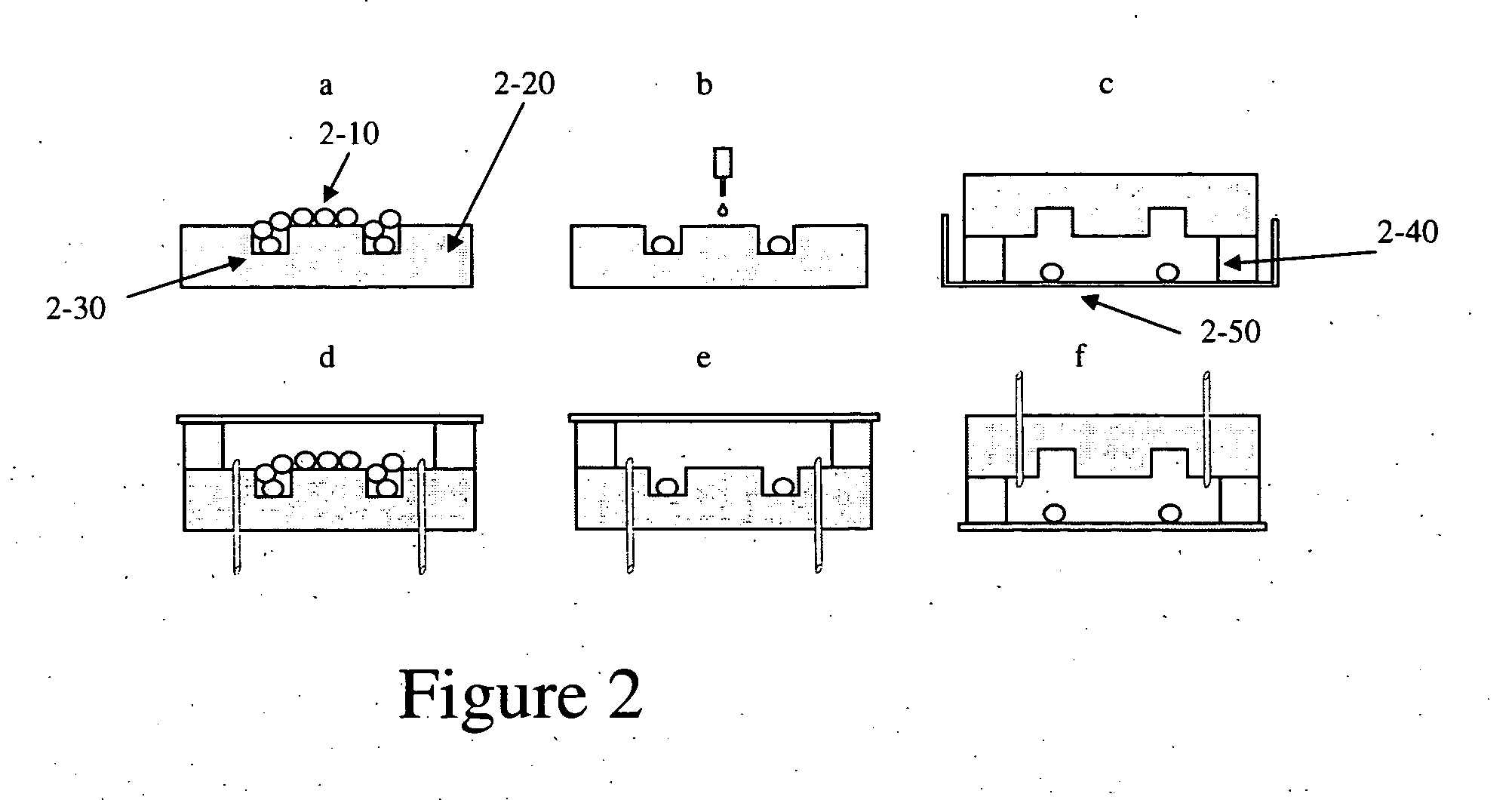
[0146]A schematic for patterning the cells is provided in FIGS. 2(a-f). Cells are pipetted onto the surface of the chip, allowing cells to fall into the microwells (FIG. 2a). After the cells are trapped in the microwells and the other cells are rinsed away (FIG. 2b), the chip is flipped upside down onto the desired substrate. This substrate can be any material—such as a glass slide, a cell-culture dish coated with another material, or another layer of cells. The cells then fall out of the microwells onto the substrate, where they attach after a few hours and proliferate (FIG. 2c). The chip has also been validated in an enclosed flow chamber (FIGS. 2d-f), enabling utilization in perfusion culture systems.
example 2
Scalability and Accuracy of the Particle Patterning Device
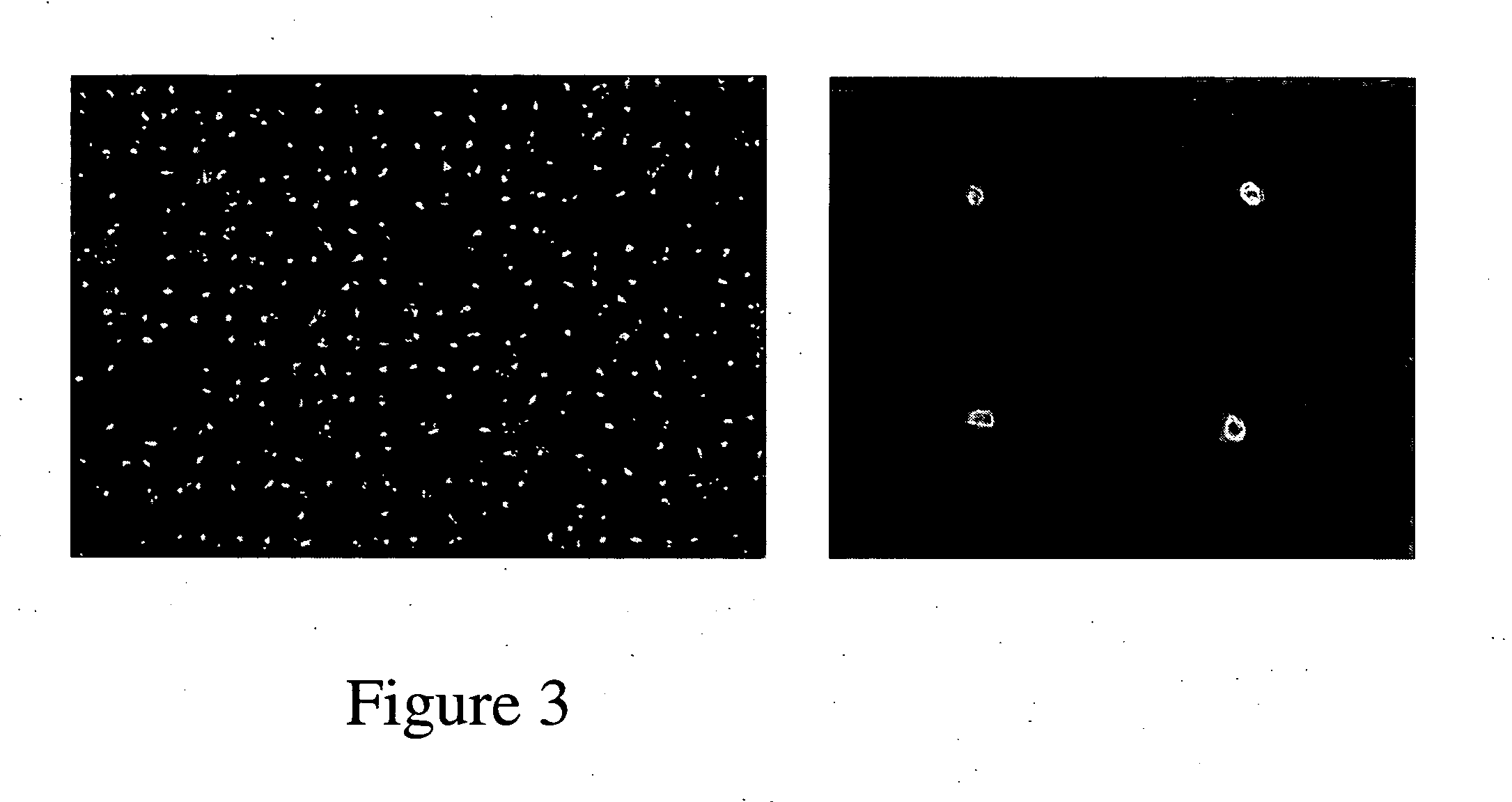
[0147]In order to determine scalability of the patterning devices, a 50×50 grid of murine embryonic stem cells were seeded onto a cell-culture dish (FIG. 3A). When multiple patterning runs of murine embryonic stem cells were applied to the device, and flipped onto a cell-culture dish, patterning efficiencies of greater than 75.9% were consistently achieved.
[0148]In addition, stem cell patterning showed superior accuracy (FIG. 3B). Using a microwell-microwell spacing of 200±0 μm, cells were patterned onto a cell-culture dish with a cell-cell spacing of 198±17 μm, thus seeding a cell within one cell diameter away from its target location. Cell patterning down to single-cell resolution has been achieved, with 50.0% of the patterned spots resulting in single cells.
[0149]Since cell-cell spacing on the grid can be varied using the devices of this invention, the seeding density of patterned cells can also be varied. In addition, the...
example 3
Long-Term Cell Tracking can be Achieved with the Patterning Devices
[0150]Proliferating cells can be patterned with the devices of this invention, and long-term studies a desirable application. Since substrate modification techniques are not necessary for the preparation of the devices of this invention, the cells are not restricted in terms of available area to grow, hence they can proliferate over a long time course, once applied to the second substrate. In addition, because the cells are patterned in a grid, the cell coordinates can be used to track the cells over time, an example of which was validated in FIG. 4. The devices of the invention provide for the ability to monitor changes in cell behavior at the single-cell level, tracking spatial and temporal changes, enabling advantages over populational averaging.
PUM
 Abstract
Description
Claims
Application Information
 - Generate Ideas
- Intellectual Property
- Life Sciences
- Materials
- Tech Scout
- Unparalleled Data Quality
- Higher Quality Content
- 60% Fewer Hallucinations
Browse by: Latest US Patents, China's latest patents, Technical Efficacy Thesaurus, Application Domain, Technology Topic, Popular Technical Reports.
© 2025 PatSnap. All rights reserved.Legal|Privacy policy|Modern Slavery Act Transparency Statement|Sitemap|About US| Contact US: help@patsnap.com