Apparatus and methods for repair of a cardiac valve

a technology for cardiac valves and apparatuses, applied in the field of apparatus and methods for repair of cardiac valves, can solve the problems of valves being damaged, valves being repaired or replaced, and distortion of the normal shape of the valve orifi

Inactive Publication Date: 2007-10-11
THE CLEVELAND CLINIC FOUND
View PDF28 Cites 176 Cited by
  • Summary
  • Abstract
  • Description
  • Claims
  • Application Information

AI Technical Summary

Benefits of technology

[0013] In accordance with another aspect of the present invention, an apparatus for repairing a cardiac valve comprises an annuloplasty ring including an expandable support member having oppositely disposed proximal and distal end portions and a main body portion between the end portions. The proximal end portion of the expandable support member comprises a plurality of wing members that extend from the main body portion. Each of the wing members includes at least one hook member for embedding into a cardiac wall and the valve annulus to secure the annuloplasty ring in the annulus of the cardiac valve. The apparatus also includes an inflatable balloon for expanding the expandable support member so that the annuloplasty ring engages the annulus of the cardiac valve. The apparatus further includes an energy delivery mechanism for selectively contracting the annuloplasty ring and thereby restricting the valve annulus to support the annulus and correct valvular insufficiency. The energy delivery mechanism includes at least one energy delivery member operably secured to a portion of said inflatable balloon. The at least one delivery member is in contact with a portion of the expandable support member.
[0014] In accordance with another aspect of the present invention, a method is provided for repairing a cardiac valve. One step of the method includes providing an annuloplasty ring having an expandable support member and an energy delivery mechanism. The energy delivering mechanism includes a detachable electrical lead having distal and proximal end portions. The distal end portion includes a securing member for attaching the distal end portion to a portion of the expandable support member, and the proximal end portion is operably connected to an energy delivery source. The securing member is attached to the portion of the expandable support member and th

Problems solved by technology

Both of these valves are subject to damage that requires that the valve be repaired or replaced.
Many of these defects are associated with dilation of the valve annulus.
This dilatation not only prevents competence of the valve, but also results in distortion of the normal shape of the valve orifice.
As a result, the heart has to work harder by pumping not only the regular volume of the blood, but also the extra volume of blood that regurgitated back into the left atrium.
The added workload creates an undue strain on the left ventricle.
This strain

Method used


Image

  • Apparatus and methods for repair of a cardiac valve
  • Apparatus and methods for repair of a cardiac valve
  • Apparatus and methods for repair of a cardiac valve

Examples


Embodiment Construction

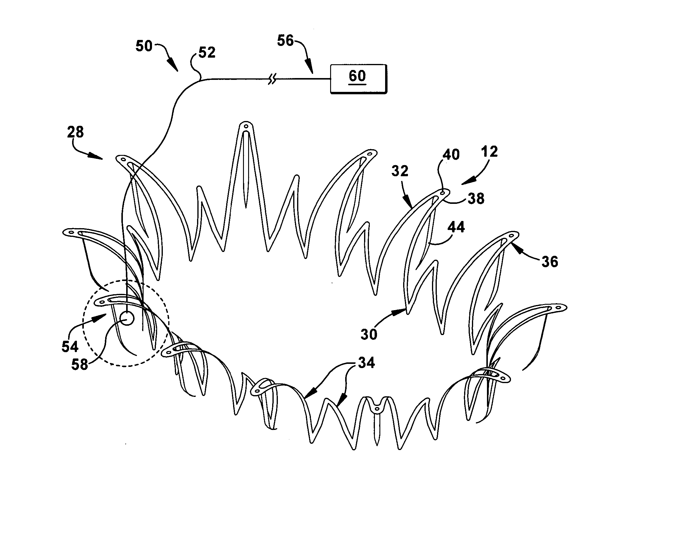
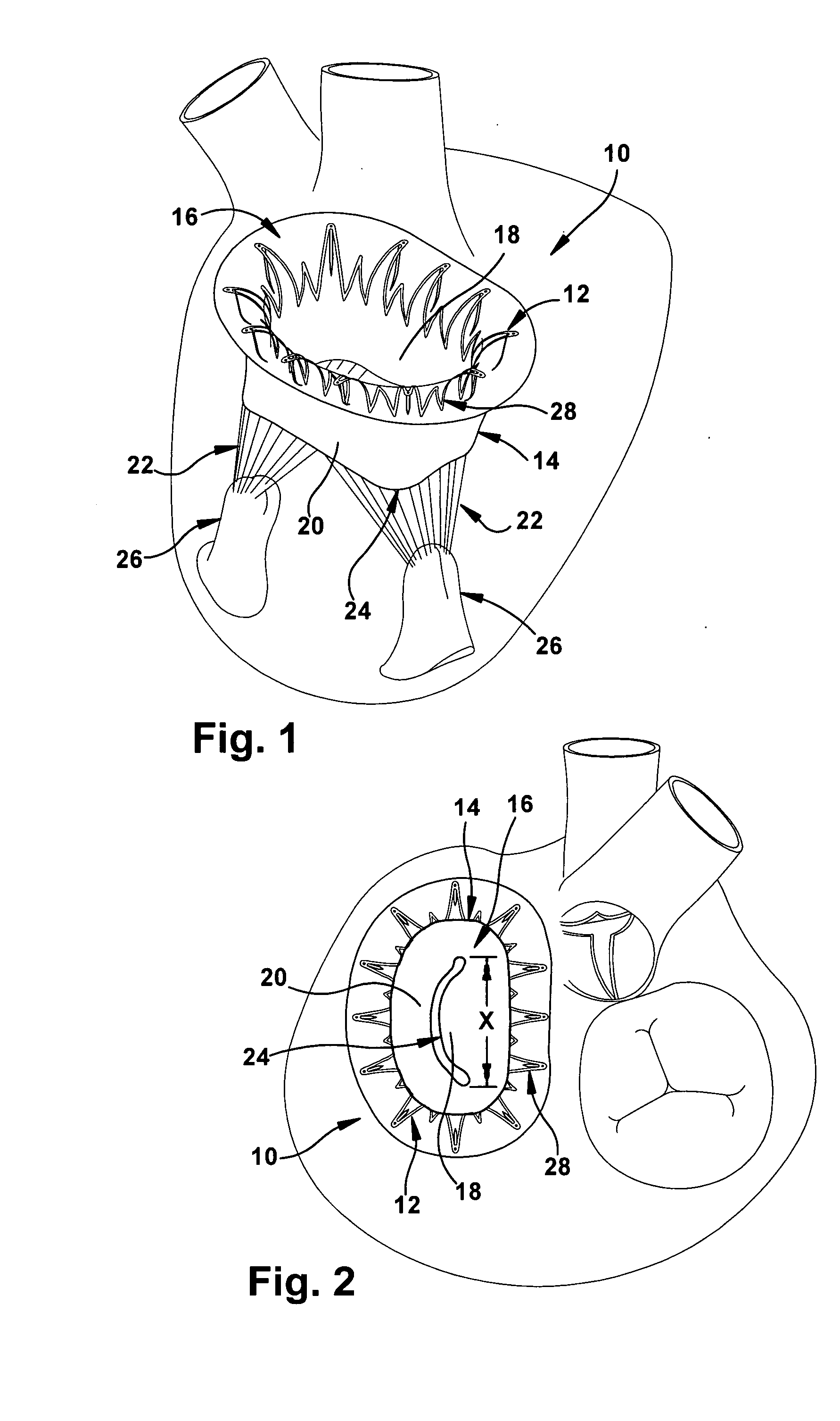
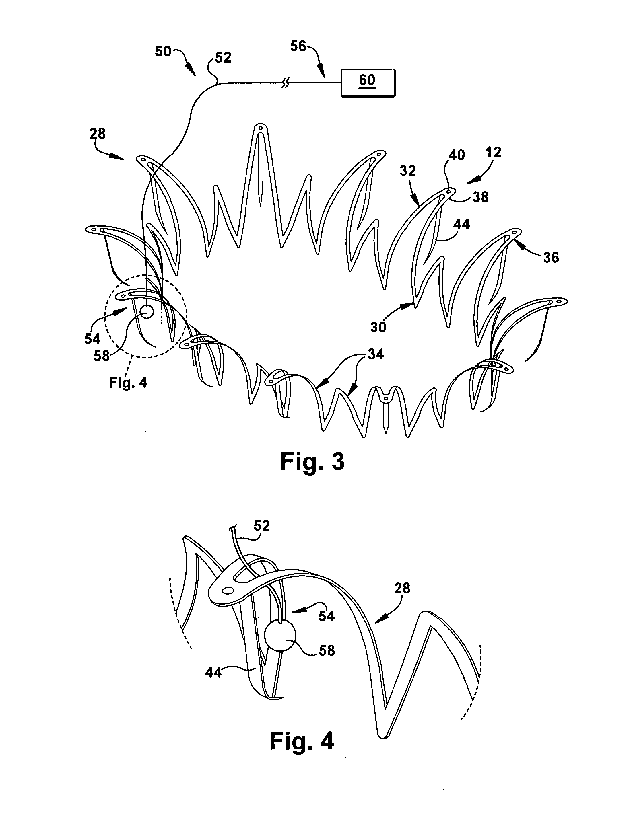
[0043] The present invention relates to an apparatus and methods for repair of a cardiac valve. As representative of the present invention, FIG. 1 illustrates an apparatus 10 that includes an annuloplasty ring 12 for repairing a dysfunctional cardiac valve, such as a mitral valve 14. It should be understood, however, that the apparatus 10 disclosed herein could be used to repair not only a mitral valve 14, but also other cardiac valves and, in particular, a tricuspid valve (not shown).

[0044] The mitral valve 14 is located between the left atrium and the left ventricle (not shown) and functions to prevent the backflow of blood from the left ventricle into the left atrium during contraction. As best seen in FIG. 2, the mitral valve 14 has a D-shaped annulus 16 that defines the opening between the left atrium and the left ventricle. The mitral valve 14 is formed by two leaflets; namely, the anterior leaflet 18 and the posterior leaflet 20. The anterior leaflet 18 extends along the gen...


PUM


Abstract

An apparatus for repairing a cardiac valve includes an annuloplasty ring having an expandable support member with oppositely disposed proximal and distal end portions and a main body portion between the end portions. The proximal end portion includes a plurality of wing members extending from the main body portion. Each of the wing members includes at least one hook member for embedding into a cardiac wall and a valve annulus to secure the annuloplasty ring therein. The apparatus also includes an energy delivery mechanism for selectively contracting the annuloplasty ring to restrict the valve annulus and correct valvular insufficiency. The energy delivery mechanism includes a detachable electrical lead having distal and proximal end portions. The distal end portion has a securing member for operably attaching the distal end portion to a portion of the expandable support member. The proximal end portion is operably connected to an energy delivery source.

Description

RELATED APPLICATIONS [0001] This application is a continuation-in-part of U.S. patent application Ser. No. 10 / 850,508, filed on May 20, 2004, which claims priority from U.S. Provisional Patent Application Ser. No. 60 / 472,030, filed on May 20, 2003, and U.S. Provisional Patent Application Ser. No. 60 / 547,416, filed on Feb. 23, 2004. The subject matter of the aforementioned applications is incorporated herein by reference in their entireties.TECHNICAL FIELD [0002] The present invention relates to an apparatus and methods for repair of a cardiac valve, and is particularly directed to an apparatus and methods that include an annuloplasty ring for the correction of mitral valve and tricuspid valve disorders. BACKGROUND OF THE INVENTION [0003] There are two atrio-ventricular valves in the heart; one on the left side of the heart and one on the right side of the heart. The left side atrio-ventricular valve is the mitral valve and the right side atrio-ventricular valve is the tricuspid valv...

Claims


Application Information

Patent Timeline
IPC IPC(8): A61F2/24A61F2/06A61F2/90
CPCA61F2/2445A61F2/91A61F2/2466
Inventor NAVIA, JOSE LUISCHEN, JI-FENG
Owner THE CLEVELAND CLINIC FOUND
Why Eureka
Try Eureka