Device and method for the geometric determination of electrical dipole densities on the cardiac wall

a technology of electrical dipole density and geometric determination, which is applied in the field of localization and can solve the problems of inaccurate current conversion methods, decreased spatial resolution, and difficulty in successful treatment of cardiac arrhythmias, and achieve the effect of improving spatial and/or time resolution of the databas

Active Publication Date: 2010-11-25
SCHARF
View PDF16 Cites 73 Cited by
  • Summary
  • Abstract
  • Description
  • Claims
  • Application Information

AI Technical Summary

Benefits of technology

[0008]In another preferred embodiment, the patient is being diagnosed and / or treated for a heart condition, such as an arrhythmia. The electrodes are included at the distal end of one or more mapping catheters and are placed into a chamber of the patient's heart to record potentials. An imaging instrument, such as an instrument that provides a generic model of a heart, or an instrument which provides an anatomical model of the patient's heart, delivers the anatomical information to the second receiver. In a preferred embodiment, the imaging instrument is one or more of: Computed Tomography; MRI; ultrasound; and an ECG system with mapping catheter.
[0009]In another preferred embodiment, the dipole density module implements an algorithm configured to assist in the creation of the database of dipole densities. The algorithm may be a progressive algorithm configured to be modified or refined to improve spatial and / or time resolution of the database. The dipole density module may determine a map of dipole densities at corresponding time intervals. A synthesis of maps represents a cascade of activation sequences of each corresponding heart beat.
[0010]In another preferred embodiment, the device includes a third receiver. The third receiver receives mapping information from one or more skin electrodes. The dipole density module uses the skin electrode signals to calculate or recalculate the database of dipole densities, using equations listed herebelow.
[0011]According to another aspect of the invention, a system for creating a database of dipole densities at the surface of one or more cardiac chambers of a patient's heart is provided. In addition to the device of the present invention, the system includes one or more of a multiple electrode catheter; an imaging instrument; an ablation device; and at least one surface or skin electrode. In a preferred embodiment, the mapping catheter is also used for ablating tissue identified by the database of dipole densities. The system includes a monitor to display the dipole density information, such as information displayed in relative geometry to the chamber of the patient's heart.
[0012]According to another aspect of the invention, a method of creating a database of dipole densities at the surface of one or more cardiac chambers of a patient's heart is provided. The method can be used to diagnose and / or treat cardiac disease. In a preferred embodiment, the method is used to diagnose and treat Atrial Fibrillation (AF). In another preferred embodiment, the method is used to detect ventricular ischemia and / or quantify myocardial function. The method includes placing an array of multiple electrodes within a chamber of the patient's heart to measure potentials. The array of multiple electrodes may or may not be repositioned to determine dipole densities.
[0013]In another preferred embodiment, the method further includes placing one or more skin electrodes. The information recorded by the skin electrodes is used to determine the database of dipole densities.

Problems solved by technology

The current conversion methods are inaccurate, and further processing, termed regularization methods, have to be used.
These regularization methods decrease spatial resolution.
Another limitation of the current methods is that the provided potentials represent only the mean electrical activity that emanates from different cells, consisting of membranes separating electrical dipoles.
Since the localization of cardiac arrhythmias by the use of potentials is imprecise, the successful treatment of cardiac arrhythmias has been difficult and has demonstrated limited success and reliability.

Method used


Image

  • Device and method for the geometric determination of electrical dipole densities on the cardiac wall
  • Device and method for the geometric determination of electrical dipole densities on the cardiac wall
  • Device and method for the geometric determination of electrical dipole densities on the cardiac wall

Examples


Embodiment Construction

[0018]Reference will now be made in detail to the embodiments in accordance with aspects of the present invention, examples of which are illustrated in the accompanying drawings. Wherever possible, the same reference numbers will be used throughout the drawings to refer to the same or like parts.

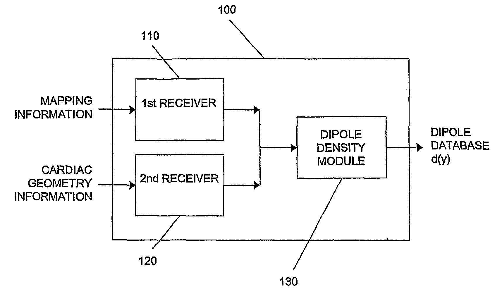
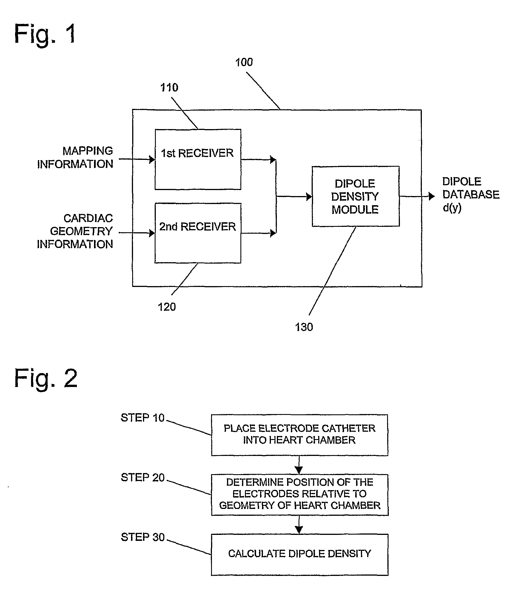
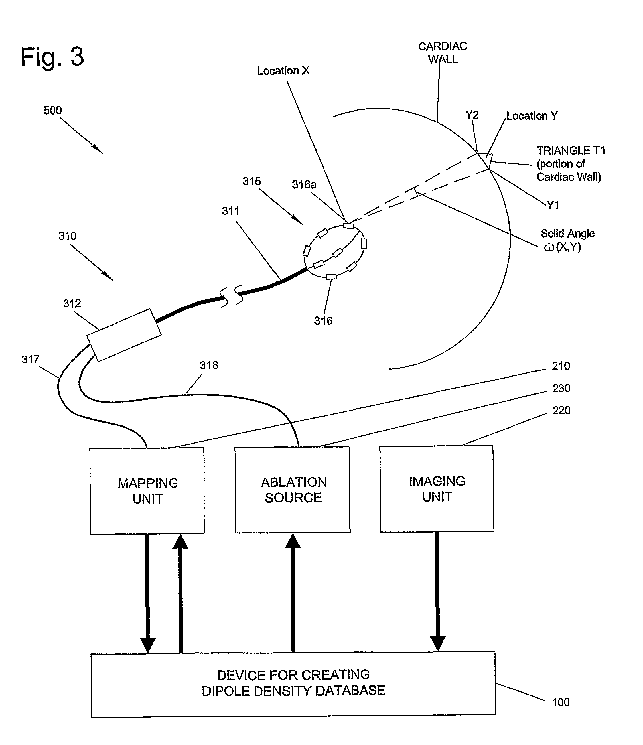
[0019]A device for calculating surface charge densities has been described in detail in PCT International Application Number PCT / CH2007 / 000380 (hereinafter the '380 patent application) naming Scharf as inventor, filed Aug. 3, 2007, and entitled METHOD AND DEVICE FOR DETERMINING AND PRESENTING SURFACE CHARGE AND DIPOLE DENSITIES ON CARDIAC WALLS, and is incorporated by reference herein in its entirety. The present invention provides an improved device, system and method for calculating and visualizing the distribution and activity of dipole charge densities on a cardiac wall. The dipole densities are directly determined geometrically, avoiding the errors encountered using previous extrapolati...


PUM


Abstract

Disclosed are devices, a systems, and methods for determining the dipole densities on heart walls. In particular, a triangularization of the heart wall is performed in which the dipole density of each of multiple regions correlate to the potential measured at various locations within the associated chamber of the heart. To create a database of dipole densities, mapping information recorded by multiple electrodes located on one or more catheters and anatomical information is used. In addition skin electrodes may be implemented.

Description

FIELD OF THE INVENTION[0001]The present invention relates generally to the localization and treatment of cardiac arrhythmias, and more particularly to devices and methods for the geometric determination of electrical dipole densities on the cardiac wall.BACKGROUND[0002]Systems used to localize the origin of cardiac arrhythmias measure potentials (e.g. in millivolts) in the cardiac chambers and localize them on a three dimensional representation of the cardiac chamber wall. The measurement of the electrical activity present on the cardiac walls is called mapping. For this purpose, a multiple electrode mapping catheter may be positioned within the heart such that multiple potentials can be simultaneously measured at different locations on the wall of the cardiac chamber without having direct wall contact (non-contact mapping). The cardiac chamber is visualized as a three dimensional structure, either directly by moving one or more mapping electrodes within the corresponding heart cham...

Claims


Application Information

Patent Timeline
Patent Type & Authority Applications(United States)
IPC IPC(8): A61B5/05A61B5/361
CPCA61B5/0422A61B18/18A61B18/0206A61B8/13A61B5/6852A61N7/00A61B5/4836A61B5/0432A61B5/02028A61B6/032A61B5/0036A61B5/242A61B5/287A61B5/318A61B5/316A61B5/333A61B5/339A61B5/361A61B18/02A61B18/12A61B2018/00351A61B2018/00577
Inventor SCHARF, CHRISTOPH
Owner SCHARF
Why Eureka
Try Eureka