
Intervertebral disc nucleus replacement implants and methods

Inactive Publication Date: 2007-10-11
WARSAW ORTHOPEDIC INC
View PDF20 Cites 62 Cited by
  • Summary
  • Abstract
  • Description
  • Claims
  • Application Information

AI Technical Summary

Benefits of technology

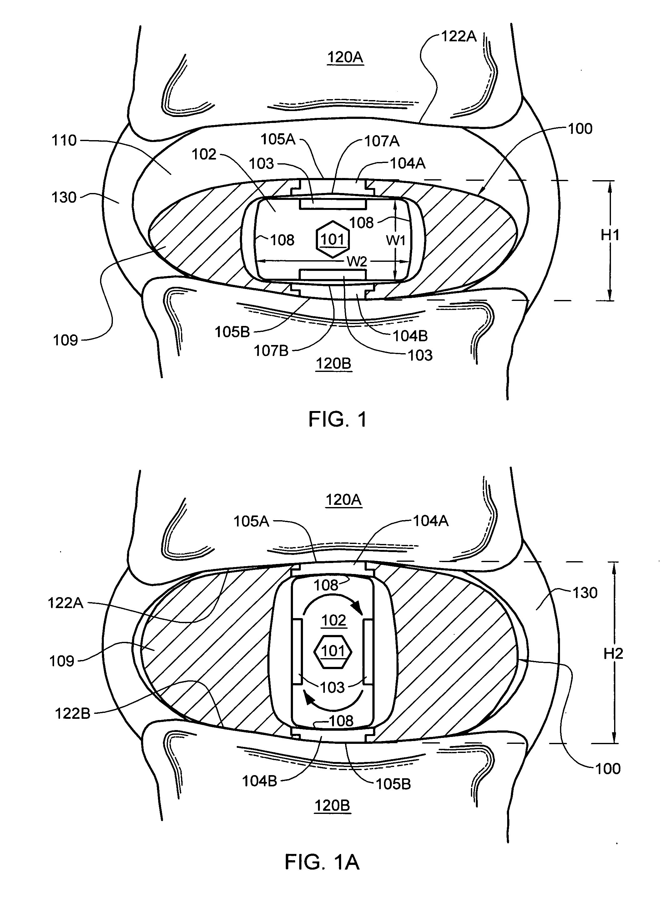
[0017] In certain enhanced aspects, the rotatable member of the nucleus replacement implant has a first width W1 in a first dimension and a second width W2 in a second dimension, with W2>W1, and wherein when the nucleus replacement implant is disposed within the intervertebral disc nucleus space and the rotatable member is in the first orientation, width W1 of the rotatable member is oriented substantially vertical within the intervertebral disc nucleus space, and when in the second orientation, width W2 of the rotatable member is oriented substantially vertical. Further, the rotatable member may comprise one of: a barrel-shaped member, a cam-shaped member, a cylindrical-shaped member, an elliptical-shaped member, a rectangular-shaped member, or a tubular-shaped member, etc. The rotatable member, which can be fabricated of metal, a non-elastic biocompatible material, or an elastic polymer of higher stiffness than the surrounding elastic body, includes at least one opening configured for facilitating rotating of the rotatable member once positioned within the intervertebral disc nucleus space. Still further, the elastic body of the nucleus replacement implant may include a centrally-disposed chamber comprising intersecting horizontally oriented and vertically oriented chambers. With such a structure, the rotatable member is in the first orientation when positioned within the horizontally oriented chamber, and is in the second orientation when positioned within the vertically oriented chamber. The elastic body defines the horizontally oriented chamber and the vertically oriented chamber, and assists in maintaining the rotatable member in one of the first orientation and the second orientation.
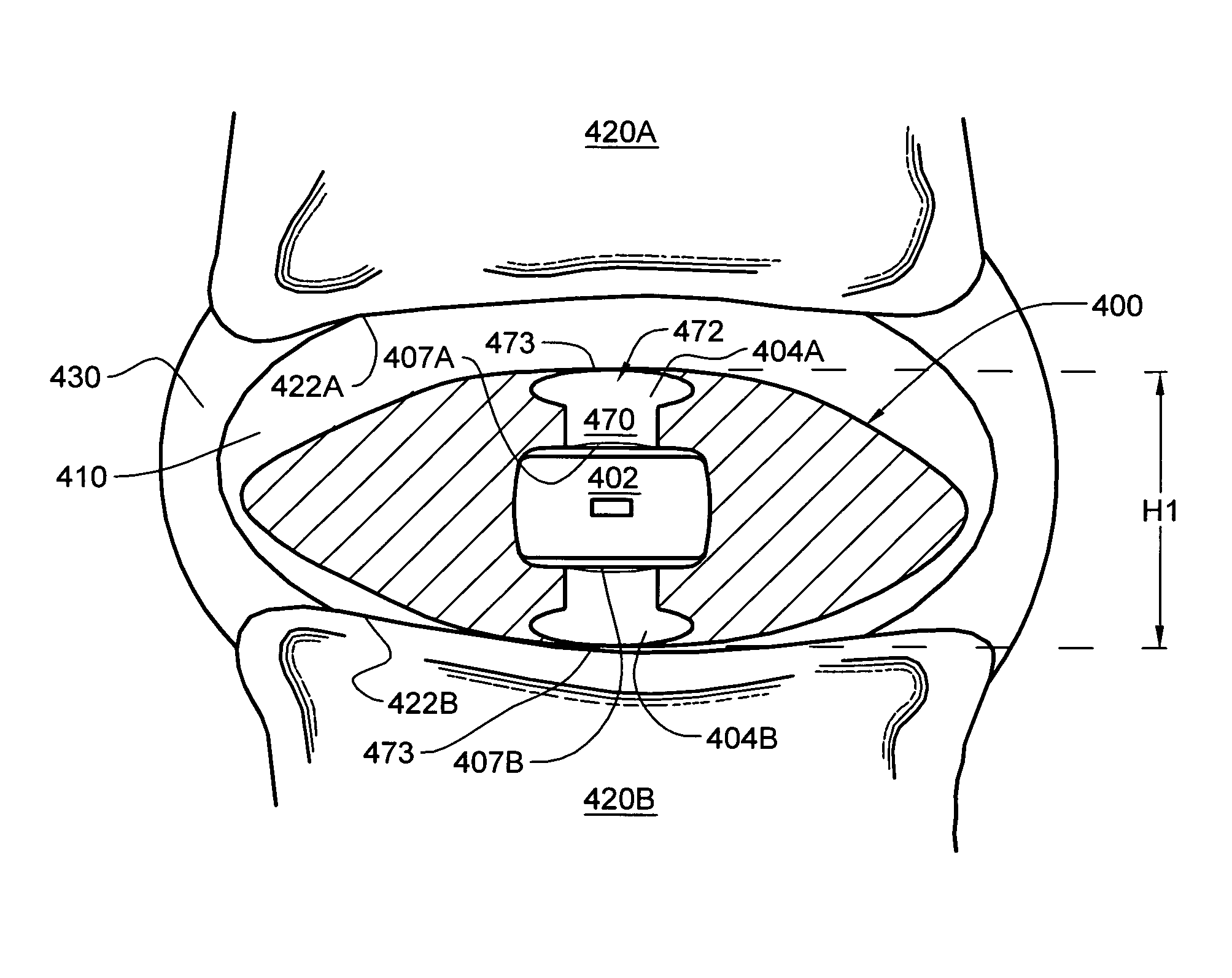
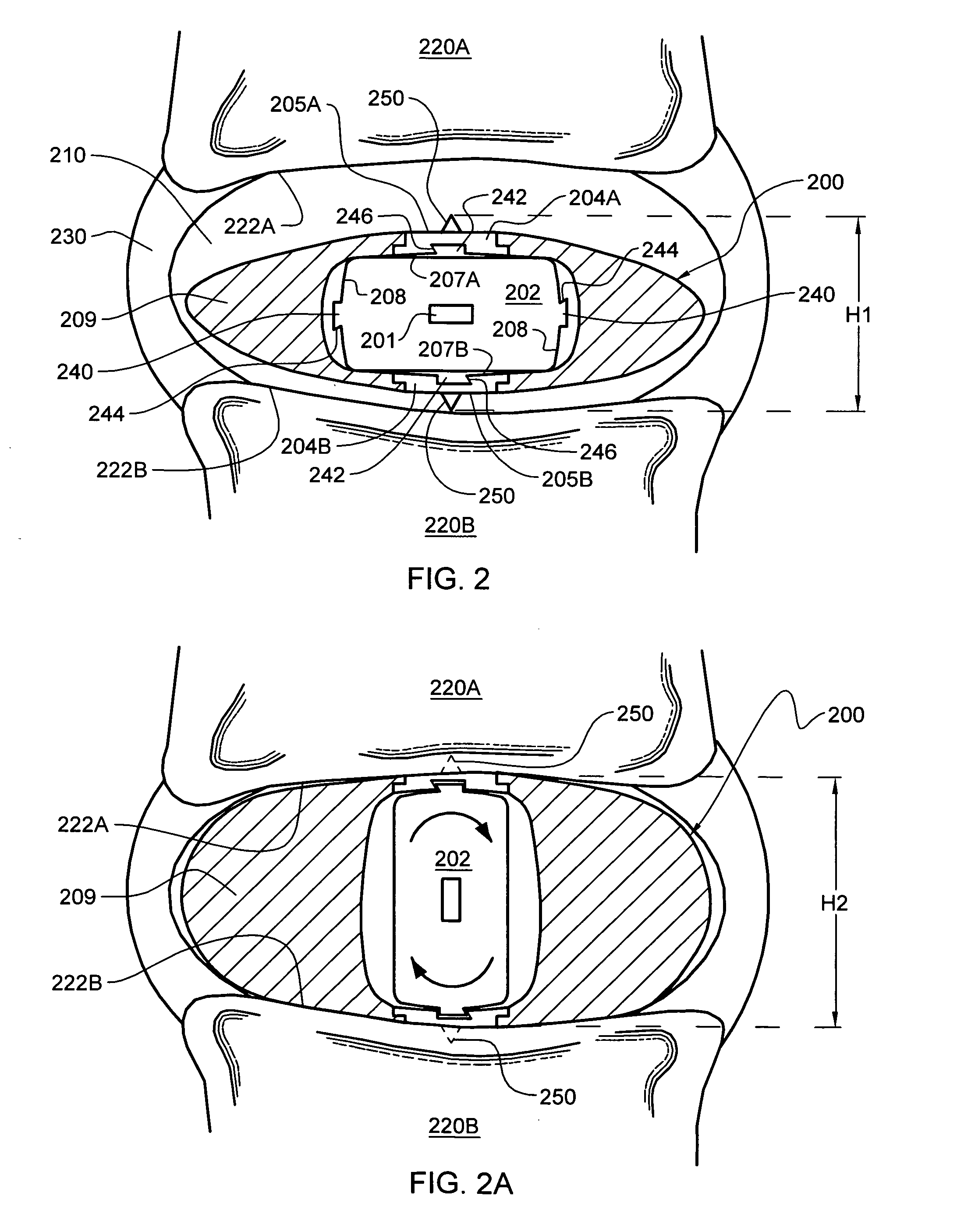
[0018] In another aspect, an intervertebral disc nucleus replacement implant is provided configured to reside within an intervertebral disc nucleus space. This implant includes a core support structure comprising a rotatable member and two vertebral support structures. The rotatable member is rotatable between a first orientation and a second orientation, and the vertebral support structures are disposed in spaced relation with the rotatable member positioned therebetween. The implant further includes an elastic body comprising biocompatible material at least partially surrounding the core support structure. When the rotatable member is in the first orientation, the nucleus replacement implant is in a compressed height configuration of height H1 to facilitate insertion of the nucleus replacement implant into the intervertebral disc nucleus space, and when the rotatable member is in the second orientation, the nucleus replacement implant is in an extended height configuration of height H2, wherein H2>H1, to facilitate use of the nucleus replacement implant as a prosthetic intervertebral disc nucleus replacement.

Problems solved by technology

It is known that intervertebral discs are prone to injury and degeneration.
For example, herniated discs are common, and typically occur when normal wear, or exceptional strain, causes a disc to rupture.
Degenerative disc disease typically results from the normal aging process, in which the tissue gradually looses its natural water and elasticity, causing the degenerated disc to shrink and possibly rupture.
One problem with such implants is that they require a relatively large hole to be cut in the disc annulus to allow introduction of the implant.
This complicates the procedure, adding surgical time and cost, and leaving a less sound annulus when the procedure is complete.
Another problem with such implants is the possibility of tearing or otherwise damaging the hydrogel implant during implantation.
Moreover, once positioned in the disc space, many hydrogel implants may migrate in the disc space and / or may be expelled from the disc space through an annular defect, or other annular opening.

Method used


Image

  • Intervertebral disc nucleus replacement implants and methods
  • Intervertebral disc nucleus replacement implants and methods
  • Intervertebral disc nucleus replacement implants and methods

Examples


example

[0069] A medical patient may be treated to replace a damaged or degenerated lumbar intervertebral disc nucleus using the procedure described above.

[0070] A / P and M / L radiographs are obtained to determine the size and shape of the affected level. The largest implant that can be accommodated by patient anatomy without overdistraction is selected, choosing (for example) among implants having footprints of 19 mm×23 mm to 22 mm×27 mm, and a height of between 6 mm and 14 mm. It is important to select the tallest device that can be accommodated by the interbody space. Excessive annulus laxity may cause non-central seating of the implant. X-ray templates are used to determine whether a small or large device footprint should be used, as are AP and ML implant outlines to determine the appropriate height.

[0071] The patient is placed in a direct prone position on the operating table, bolstered appropriately to maintain lumbar lordosis. C-arm fluoroscopy is not absolutely necessary for the pro...


PUM

PropertyMeasurementUnit
Sizeaaaaaaaaaa
Widthaaaaaaaaaa
Heightaaaaaaaaaa

Abstract

Intervertebral disc nucleus replacement implants and methods are provided. The nucleus replacement implant, which is configured to reside within an intervertebral disc nucleus space, includes a core support structure, including a rotatable member and multiple vertebral support structures. The vertebral support structures are disposed in spaced relation with the rotatable member positioned therebetween. The implant further includes an elastic body at least partially surrounding the core support structure. When the rotatable member is in the first orientation, the implant is in a compressed height configuration to facilitate insertion of the implant into the intervertebral disc nucleus space, and when the rotatable member is in the second orientation, the implant is in an extended height configuration to facilitate use of the implant as a prosthetic intervertebral disc nucleus replacement.

Description

CROSS-REFERENCE TO RELATED APPLICATIONS / PATENTS [0001] This application contains subject matter which is related to the subject matter of the following applications / patents, which are hereby incorporated herein by reference in their entirety: [0002]“Instruments and Methods for Implanting Nucleus Replacement Material in an Intervertebral Disc Nucleus Space”, Allard et al., U.S. Ser. No. 11 / 343,088, filed Jan. 30, 2006; [0003]“Method and Apparatus for Delivering an Intervertebral Disc Implant”, Trieu et al., U.S. Ser. No. 10 / 717,687, filed Nov. 20, 2003, and published on Jun. 17, 2004 as Patent Application Publication No. US 2004 / 0117019 A1; [0004]“Method and Apparatus for Delivering an Intervertebral Disc Implant”, Trieu et al., Patent Cooperation Treaty Application No. PCT / US2004 / 038750, and published on Jun. 9, 2005 as International Publication No. WO 2005 / 051246 A2; [0005]“Intervertebral Disc Nucleus Implants and Methods”, Hai H. Trieu, U.S. Ser. No. 09 / 943,411, filed Aug. 30, 200...

Claims


Application Information

Patent Timeline
IPC IPC(8): A61F2/44
CPCA61F2/442A61F2250/0019A61F2002/30014A61F2002/30016A61F2002/30062A61F2002/30069A61F2002/30075A61F2002/302A61F2002/30224A61F2002/30253A61F2002/30476A61F2002/30556A61F2002/30579A61F2002/30581A61F2002/30672A61F2002/30677A61F2002/30841A61F2002/444A61F2210/0004A61F2210/0061A61F2220/0025A61F2230/0065A61F2230/0069A61F2230/0076A61F2250/0009A61F2250/0018A61F2/4611
Inventor FRANCIS, THOMAS J.
Owner WARSAW ORTHOPEDIC INC
Learn More