Fluid circuit with multiple flows from a series valve

Active Publication Date: 2007-10-18
CLARK EQUIP CO INC
View PDF12 Cites 5 Cited by
  • Summary
  • Abstract
  • Description
  • Claims
  • Application Information

AI Technical Summary

Problems solved by technology

Different functions can have different application or system parameters, such as different flow parameters, making it difficult to energize or operate different functions using a single pump or a multifunction valve stack.

Method used


Image

  • Fluid circuit with multiple flows from a series valve
  • Fluid circuit with multiple flows from a series valve
  • Fluid circuit with multiple flows from a series valve

Examples


Embodiment Construction

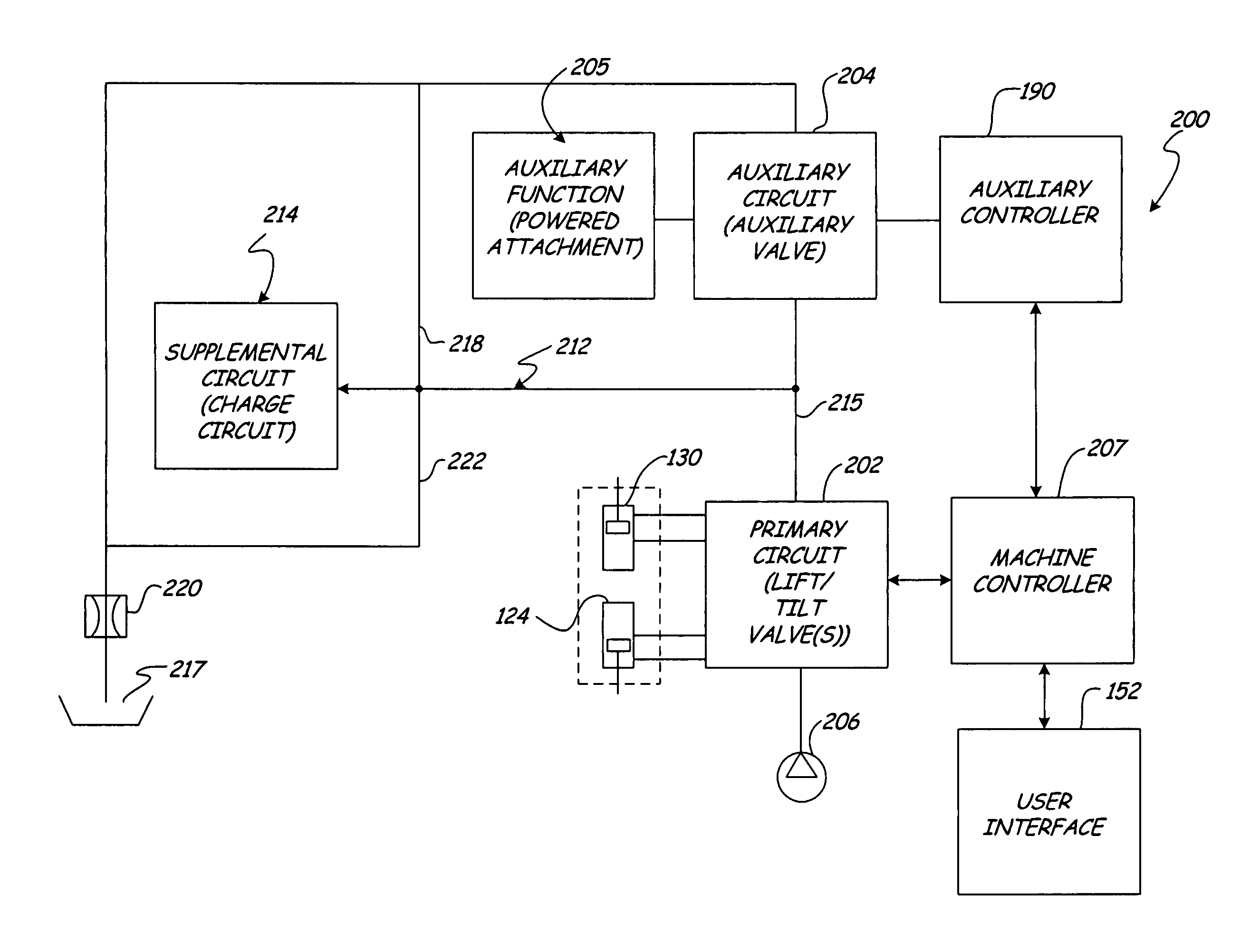
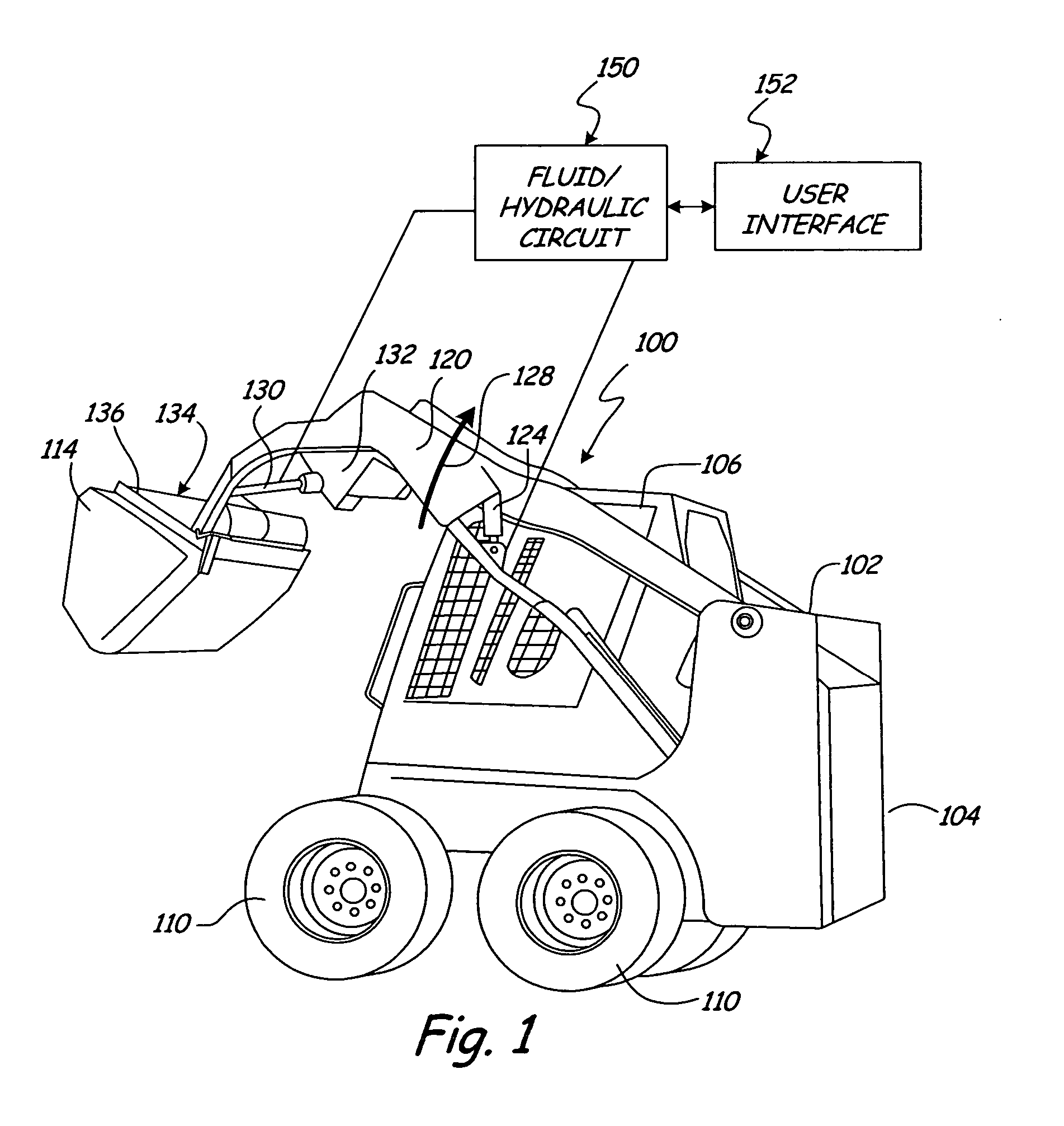
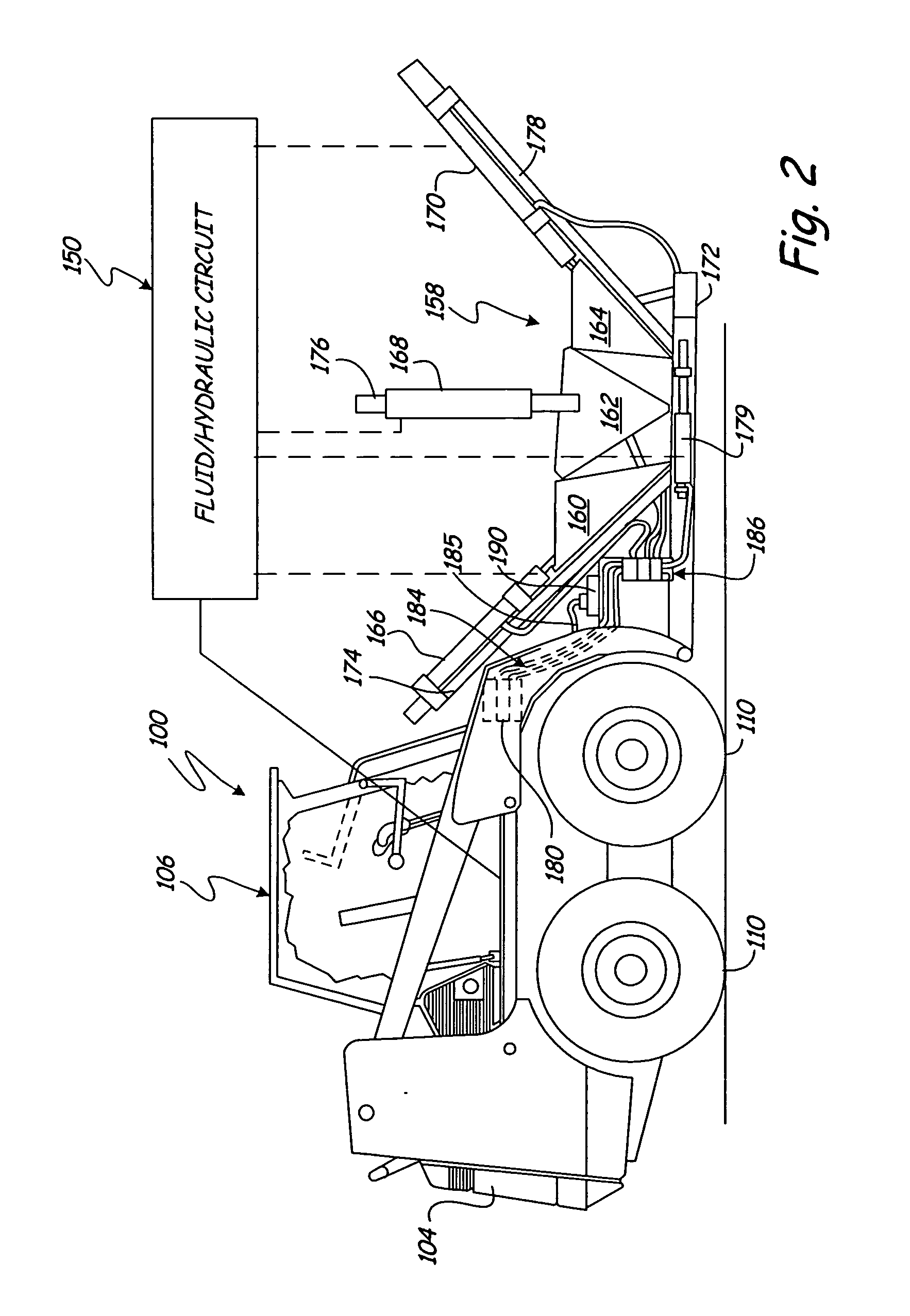
[0008] The present invention relates to a fluid or hydraulic circuit to operate functions or an attachment of a power machine or vehicle of the types illustrated in FIGS. 1 and 2. Application, however of the present invention is not limited to the particular vehicles shown in FIGS. 1 and 2.

[0009] In the embodiment illustrated in FIG. 1, the power machine 100 includes a body 102, an engine compartment 104, and an operator cab 106. The body 102 of the vehicle is supported relative to a frame (not shown). Wheels 110 are coupled to the frame so that the power machine 100 or vehicle can move over the ground during use. Application, however, of the present invention is not limited to a wheeled vehicle or loader as shown. For example, the present invention has application for a power machine which moves along a track instead of wheels.

[0010] In the embodiment illustrated in FIG. 1, the machine includes a bucket 114 coupled to lift arms 120 (only one shown in FIG. 1). Lift arms 120 are pi...


PUM


Abstract

A circuit or system having application for operating an implement or attachment for a power machine is disclosed. The circuit includes a first or primary valve, a second or auxiliary valve connected in series with the first valve and a supplemental line connected in parallel with the second valve to provide fluid to a supplemental system in parallel with the second valve.

Description

BACKGROUND OF THE INVENTION [0001] The present invention relates to a fluid or hydraulic circuit. Fluid or hydraulic circuits are employed to activate or control functions of a power machine. Hydraulic fluid is supplied by a pump to power various machine functions, such as lift, tilt or powered attachment. Fluid flow to various machine functions is controlled by valves or a valve stack. Different functions can have different application or system parameters, such as different flow parameters, making it difficult to energize or operate different functions using a single pump or a multifunction valve stack. The present invention addresses these and other problems and provides advantages not previously recognized nor appreciated. SUMMARY [0002] The present invention relates to a fluid or hydraulic circuit having application for a power machine. As shown, the circuit includes a first valve, a second valve connected in series with the first valve and a supplemental line connected in para...

Claims


Application Information

Patent Timeline
IPC IPC(8): F16D31/02B66C23/00
CPCE02F9/2221E02F9/2282F15B2211/88F15B21/14F15B2211/76F15B1/16
Inventor MAUCH, ADAM R.SHELBOURN, WILLIAM C.ST. AUBIN, JOSEPH A.BROCK, KNUTE K.KACZMARSKI, WALLY L.
Owner CLARK EQUIP CO INC
Why Eureka
Try Eureka