
Legged Robot and Legged Robot Walking Control Method

Inactive Publication Date: 2007-10-18
TOYOTA JIDOSHA KK
View PDF18 Cites 35 Cited by
  • Summary
  • Abstract
  • Description
  • Claims
  • Application Information

AI Technical Summary

Benefits of technology

[0017] Based on circumstances described above, technology, which does not need a force sensor mounted on the leg tip and is able to stabilize walking with simpler constitution, is deemed necessary to lower manufacturing costs and to enhancing the reliability of a legged robot.
[0032] According to the invention, it is possible to realize a legged robot that continues walking stably without using force sensors in its leg tips. A highly reliable legged robot can be achieved inexpensively.

Problems solved by technology

A 6-axis force sensor or other such high-performance force sensor is expensive.
When a sensor is mounted on the proximity of the leg tip, the sensor is apt to malfunction as a result of impact.
When a sensor mounted on the proximity of the leg tip malfunctions, the robot is not able to continue walking.
If any one of these parts malfunctions, the signal from the force sensor cannot be properly transmitted to the processing part, resulting in a state wherein the force sensor does not function.

Method used


Image

  • Legged Robot and Legged Robot Walking Control Method
  • Legged Robot and Legged Robot Walking Control Method
  • Legged Robot and Legged Robot Walking Control Method

Examples


first embodiment

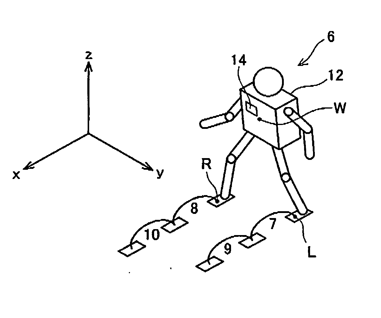
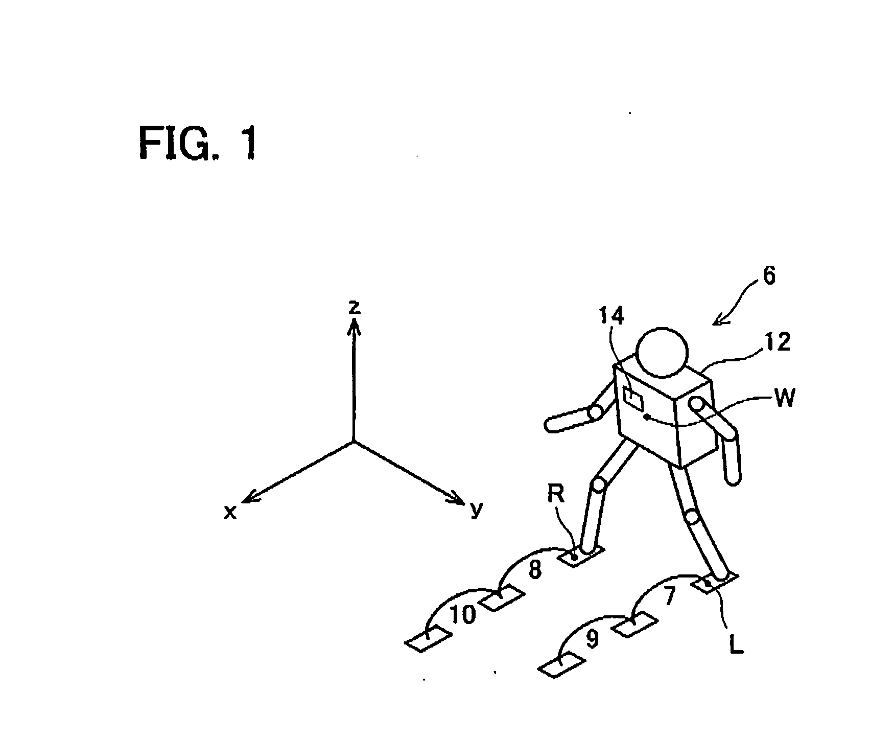
[0046] The robot 6 shown in FIG. 1 moves the left leg as the floating leg along a trajectory 7 while the right leg is planted on the ground, and then, when the left leg is planted on the ground, moves the right leg as the floating leg along a trajectory 8, and similarly thereafter continues walling by moving the left leg as the floating leg along a trajectory 9, and subsequently moving the right leg as the floating leg along a trajectory 10.

[0047] In order for the robot 6 to continue walking, gait data is required, which is constituted from leg tip trajectory data describing the trajectories 7, 8, 9, 10 of the leg tip reference points L, R, hand trajectory data, and torso trajectory data describing the trajectory of a reference point W on the torso 12. Leg tip trajectory data is specified by an operator. Hand trajectory data is computed corresponding to the leg tip trajectory data. Torso trajectory data is set to a relationship in which a ZMP trajectory computed using a robot dynam...

second embodiment

[0105] A robot may be equipped with a device for detecting the torso position. For example, if a gyroscope is mounted on the robot, it is possible to detect not only the actual torso acceleration, but also the actual torso position. Mounting a GPS measurement sensor also makes it possible to detect the actual torso position. Torso velocity can be determined by integrating torso acceleration, and further integration will also make it possible to detect torso position.

[0106] When the robot can detect its actual torso position, a feedback control loop can be put to practical use. When the feedback control loop is utilized, it becomes possible to cope with a situation in which the robot is tilted in its entirety because the robot is walking over rough terrain. An explanation of the second embodiment will be given below, but only those points that differ from the first embodiment will be explained.

[0107]FIG. 9 shows a block diagram of the functionality of a computer of the robot of the...


PUM


Abstract

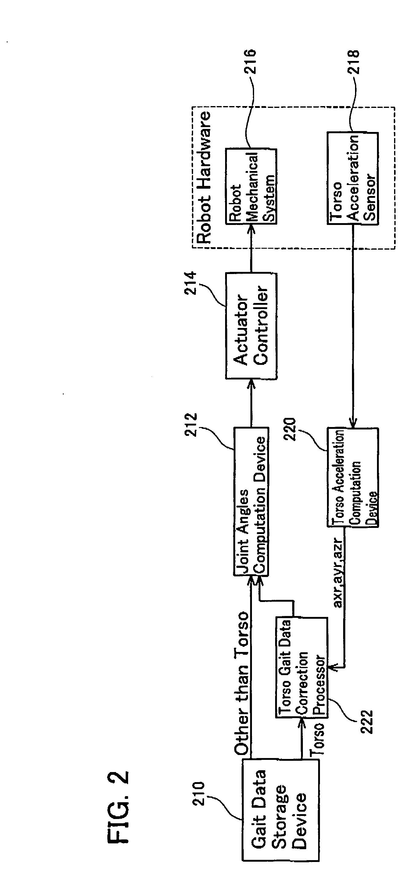
A legged robot and a legged robot walking control method are disclosed, which enable stable walking without force sensors on leg tips. A legged robot of the present invention comprises a torso, a leg link, which is swingably connected to the torso, storing means 210 for storing leg tip gait data describing a time-series change in a target leg tip motion, storing means 210 for storing torso gait data describing a time-series change in a target torso motion, which realizes a target ZMP following the change in the target leg tip motion, torso motion detection means 218, 220 for detecting an actual torso motion, deviation calculation means 312 for calculating a deviation of the actual torso motion from the target torso motion, correction quantity calculation means 308 for determining a correction quantity from the calculated deviation based on a prescribed transfer function, and correction means 306 for correcting the target torso gait data based on the determined correction quantity.

Description

CROSS-REFERENCE TO RELATED APPLICATIONS [0001] The present application claims priority based on Japanese Patent Application No. 2004-20328, filed on Jan. 28, 2004, the entire disclosure of which is incorporated herein by reference. TECHNICAL FIELD [0002] The present invention relates to technology for controlling a machine (legged robot mechanical system), to which leg links are swingably connected to a torso (trunk part), to make it walk. More specifically, the present invention relates to a legged robot and a walking control method thereof, enabling continuous stable walking even when the legged robot is affected by an unanticipated disturbance force. BACKGROUND ART [0003] Legged robots are being developed that walk by changing the relative postures among the left leg link, the torso, and the right leg link. [0004] Data that instructs the movement of the left leg tip, the torso and the right leg tip is required to make a legged robot walk. Of these, the position of the torso must ...

Claims


Application Information

Patent Timeline
IPC IPC(8): B25J5/00G06F19/00B25J13/00B62D57/032
CPCB62D57/032
Inventor YAMAMOTO, TAKASHISUGIHARA, HISAYOSHISUGA, KEISUKETSUSAKA, YUJITAJIMA, RYOSUKE
Owner TOYOTA JIDOSHA KK
Learn More