Method for measuring stability margin at a node of a polyphase power grid

a power grid and stability margin technology, applied in the field of polyphase power grid, can solve the problems of limited transmission capacity of a power grid, e.g. national power grid, and excessive sag of transmission lines, and achieve the effect of avoiding oscillatory instability

Inactive Publication Date: 2007-10-18
WILLIAMS MICHAEL LAMAR
View PDF4 Cites 45 Cited by
  • Summary
  • Abstract
  • Description
  • Claims
  • Application Information

AI Technical Summary

Benefits of technology

[0029]The present invention provides a method for providing real-time knowledge of the margin of stability at nodes of a power grid, e.g., the national power grid, thereby aiding the monitoring of the power grid to avoid oscillatory instability.

Problems solved by technology

The transmission capacity of a power grid, e.g., the national power grid, is limited by factors such as voltage stability, transient stability and oscillatory stability, in addition to thermal overload conditions that result in excessive transmission line sag.
The potential for oscillatory instability, also known as subsynchronous resonance, is of particular concern because the transition from stable to unstable conditions can be quite abrupt and may occur without warning.
In a matter of seconds, a power system that becomes small-signal unstable can transition to a condition of large amplitude voltage, current and torque fluctuation that can be highly disruptive and destructive.
Although voltage and current waveforms in the system may provide warnings of an impending instability, this is not always the case.
A slight change in operating conditions, such as a small increase in load, can cause the system to cross the threshold and suddenly experience violent excursions.
A primary cause of oscillatory instability is negative resistance.
The high efficiency and well regulated outputs that can be obtained with this technology bring with it an inherent negative resistance characteristic at the AC input that can cause oscillatory instability.
Series voltage injection tends to be invasive, requiring disruption of power flow to insert the injection transformers.
Substantial obstacles exist in the practical application of the above-described methods in the measurement of stability margin and / or impedance at nodes of the national power grid.

Method used


Image

  • Method for measuring stability margin at a node of a polyphase power grid
  • Method for measuring stability margin at a node of a polyphase power grid
  • Method for measuring stability margin at a node of a polyphase power grid

Examples


Embodiment Construction

[0055]Referring now to the drawings and particularly to FIGS. 7A-7C, there is shown a flowchart of a method for measuring a stability margin at a node of a polyphase power grid, and an impedance of a branch connected to the node, in accordance with embodiments of the present invention, as illustrated generally in FIGS. 8-15.

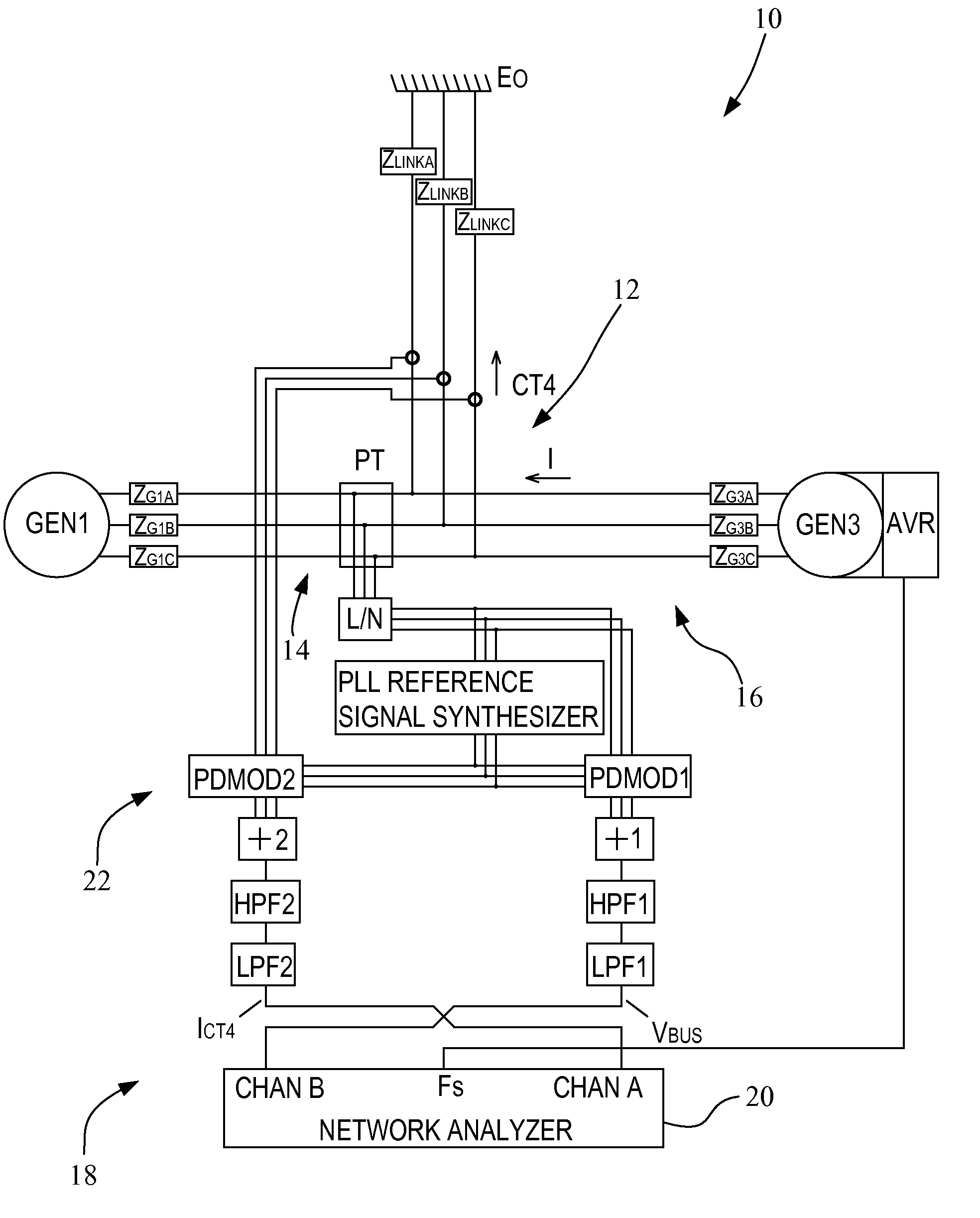
[0056]For convenience, and ease of understanding, the method of FIGS. 7A-7C will be described with particular reference to FIG. 11. In this example, FIG. 11 is an exemplary configuration that may be used in measuring stability margin (using currents ICT3 and ICT1 respectively on channels CHAN A and CHAN B), and with the inclusion of an auxiliary configuration represented by dashed lines, may be used in measuring suppressed carrier impedance (using currents ICT3 and ICT1 respectively on channels CHAN A and CHAN B, and voltage VBUS on channel CHAN C). In FIG. 11, for example, there is shown an exemplary polyphase power grid 10 to which there is attached a plurality...


PUM


Abstract

A method for measuring a stability margin at a node of a polyphase power grid injects suppressed-carrier stimulus into a node of the power grid by low-level amplitude modulation of the output voltage of a pre-exiting generator connected to the node. Response signals are obtained and product demodulated on a per-phase basis and summed in three-phase groups. Demodulated and summed responses contain signals that represent the suppressed-carrier impedance upstream and downstream of the stimulus injection point, and are processed to determine the stability margin at the node.

Description

CROSS-REFERENCE TO RELATED APPLICATIONS [0001]This is a non-provisional application based upon U.S. provisional patent application Ser. No. 60 / 790,146, entitled “MEANS OF MEASURING STABILITY MARGIN AT NODES OF THE NATIONAL POWER GRID”, filed Apr. 7, 2006.GOVERNMENT RIGHTS IN PATENT [0002]Early work on AC stability, prior to the present invention, was made with the proceeds from government contract no. N00167-96-D0045 / 0004. However, federal funding was not involved in the invention claimed herein.BACKGROUND OF THE INVENTION[0003]1. Field of the Invention[0004]The present invention relates to a polyphase power grid, and, more particularly, to a method for measuring stability margin at a node of a polyphase power grid.[0005]2. Description of the Related Art[0006]The transmission capacity of a power grid, e.g., the national power grid, is limited by factors such as voltage stability, transient stability and oscillatory stability, in addition to thermal overload conditions that result in...

Claims


Application Information

Patent Timeline
Patent Type & Authority Applications(United States)
IPC IPC(8): G01R27/00
CPCH02J3/00G01R27/32
Inventor WILLIAMS, MICHAEL LAMAR
Owner WILLIAMS MICHAEL LAMAR
Why Eureka
Try Eureka