
Liquid Container

a liquid container and liquid technology, applied in the field of liquid containers, can solve problems such as failure of the ink supply, and achieve the effects of high precision, high precision, and influence on the precision of the operation

Inactive Publication Date: 2007-10-18
SEIKO EPSON CORP
View PDF15 Cites 23 Cited by
  • Summary
  • Abstract
  • Description
  • Claims
  • Application Information

AI Technical Summary

Benefits of technology

[0047] According to the liquid container in accordance with the invention, it is possible to supply a liquid having a uniform concentration with high precision by the stirring force of the stirring and moving member without the stirring and moving member in the liquid containing portion generating a great collision sound to be a noise and generating such a vibration as to influence precision in an operation by the collision of the stirring and moving member.
[0048] According to the liquid container in accordance with the invention, moreover, it is possible to supply a liquid having a uniform concentration with high precision without the stirring and moving member accommodated in the liquid containing portion blocking the connecting passage formed on the partition wall of the liquid containing portion to disturb the circulation of the liquid in the connecting passage.
[0049] According to the liquid container in accordance with the invention, furthermore, it is possible to further enhance the stirring property of the stirring and moving member in the liquid container having the stirring and moving member for stirring the accommodated liquid.

Problems solved by technology

In the conventional ink cartridge in which the stirring and moving member is put in the ink containing portion, moreover, there is a possibility that an opening of the connecting passage for an ink supply which is formed to penetrate through the partition wall of the ink containing portion might be blocked partially or wholly by the stirring and moving member to generate an ink supply failure depending on the shape of the opening of the connecting passage or the size of the stirring and moving member.

Method used


Image

  • Liquid Container
  • Liquid Container
  • Liquid Container

Examples


Embodiment Construction

[0069] A liquid container according to the invention is suitable for supplying a liquid to a liquid ejecting head of a liquid ejecting apparatus. For example, the liquid ejecting apparatus includes a liquid ejecting head (a print head) of an ink jet type recording apparatus, a coloring agent ejecting head of a color filter manufacturing apparatus for manufacturing a color filter of a liquid crystal display, an electrode material (conductive paste) ejecting head for forming an electrode of an organic EL display or an FED (a surface emitting display), and furthermore, a bioorganism ejecting head of a biochip manufacturing apparatus for manufacturing a biochip and a specimen ejecting head to be a precision pipette.

[0070] A preferred embodiment of the liquid container according to the invention will be described below in detail with reference to the drawings. In the embodiment, description will be given to an ink cartridge to be used with an attachment or removal to / from the ink jet ty...


PUM


Abstract

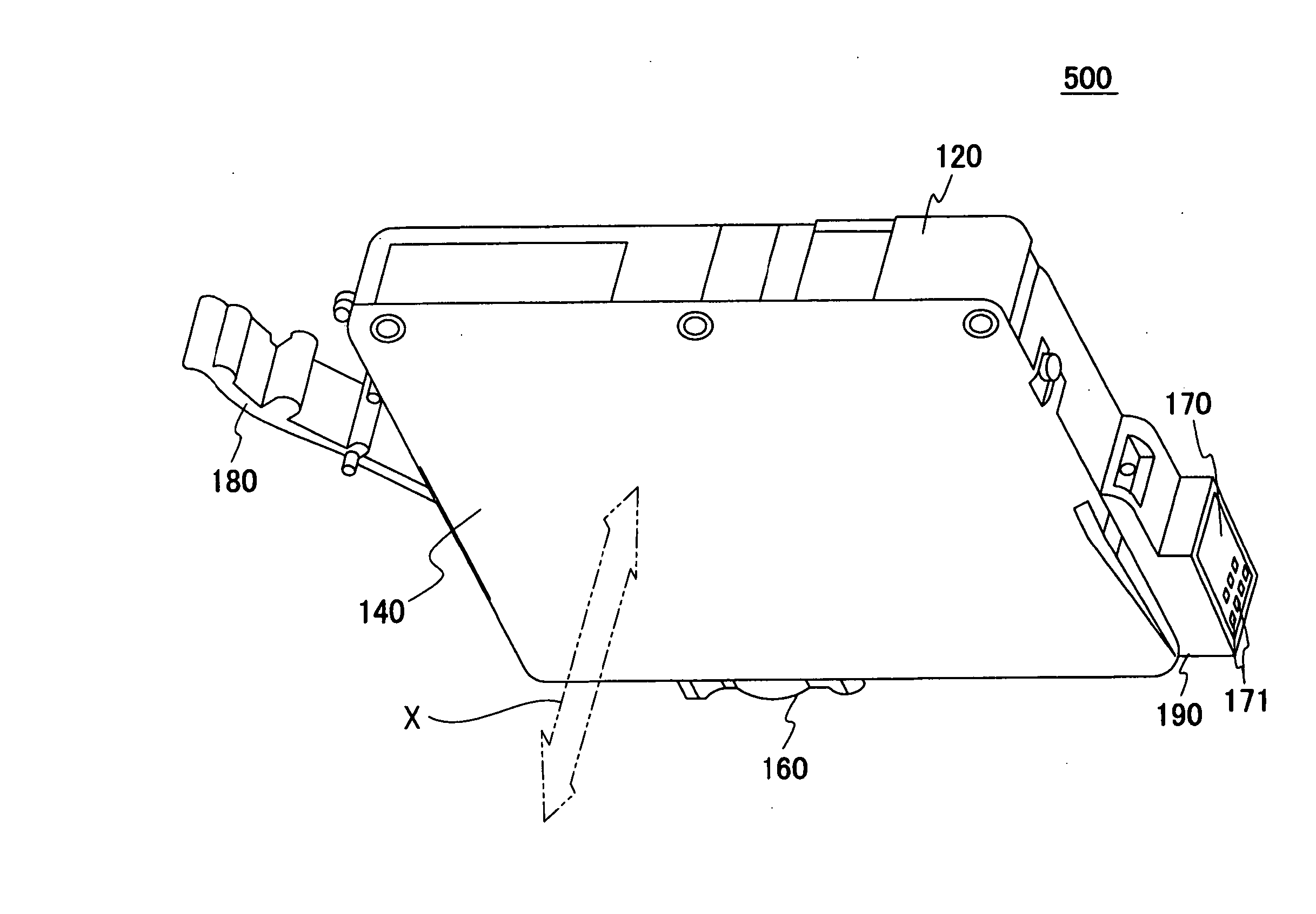
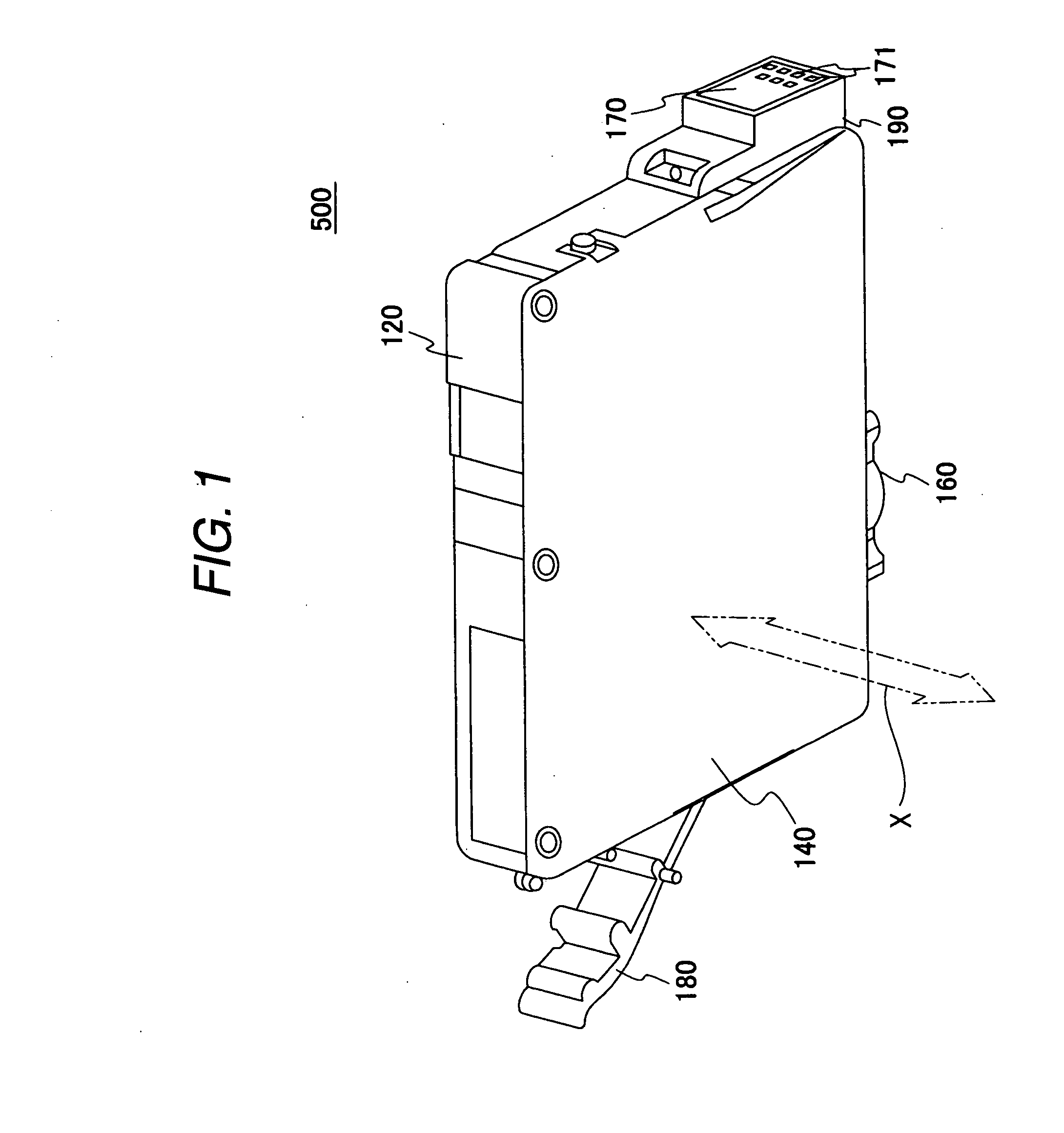
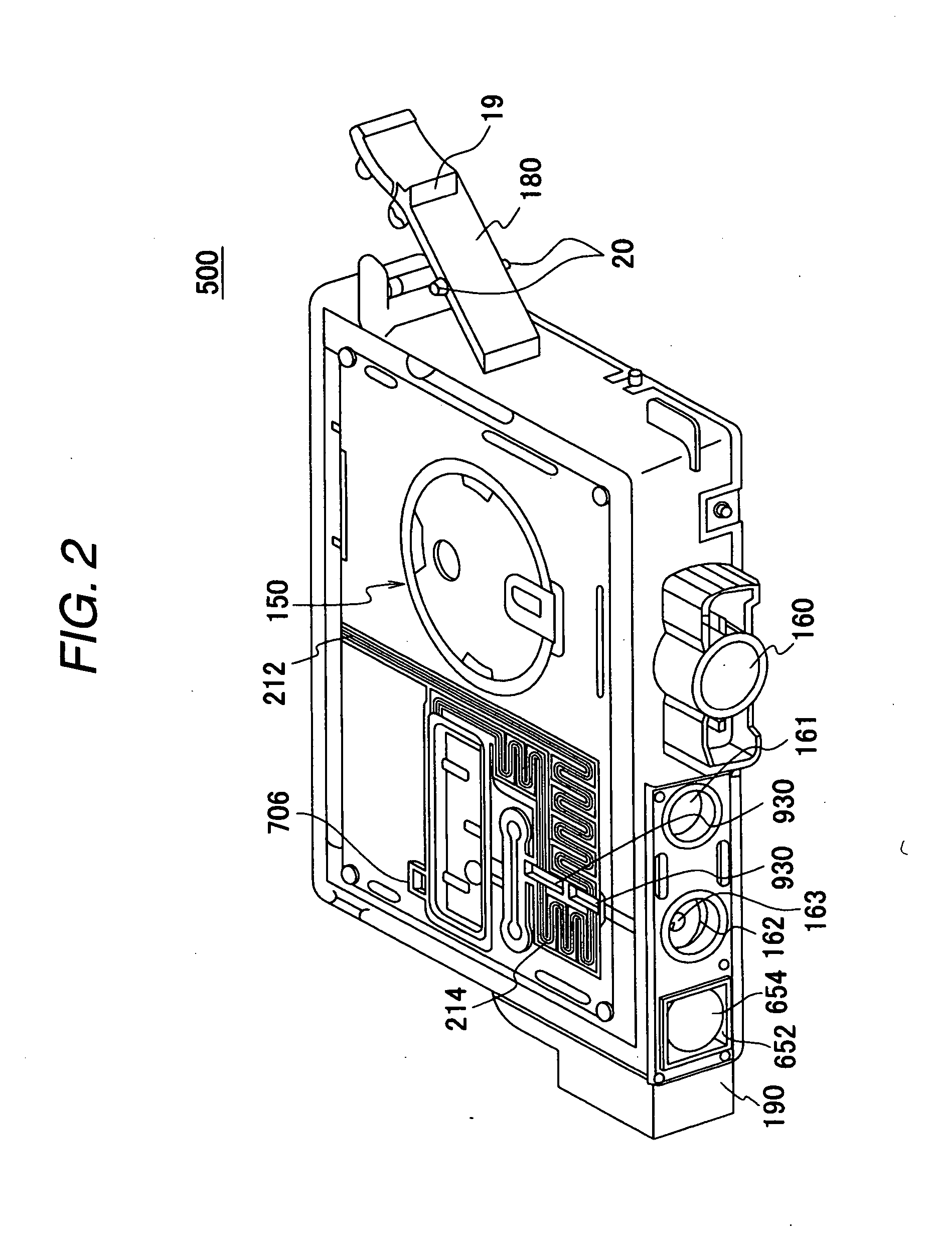
An ink cartridge 500 according to the invention is mounted on a carriage to reciprocate together with a coating head and serves to supply an ink in an air side containing portion 270 and a supply side containing portion 290 to the coating head. The air side containing portion 270 and first and second ink containing portions 292 and 294 are formed by a liquid containing concave portion 122 of a cartridge body 120 having one open surface opposed to a direction of a reciprocation of the coating head and a film 140 for sealing the open surface of the liquid containing concave portion 122. A stirring and moving member 711 is accommodated in the air side containing portion 270 and the second ink containing portion 294 in a movable state, respectively.

Description

TECHNICAL FIELD [0001] The present invention relates to a liquid container for supplying a liquid accommodated in an inner part to an outside and, for example, to a liquid container suitable as an ink cartridge attached to a carriage of an ink jet type recording apparatus and serving to supply an ink accommodated in an inner part to a print head. BACKGROUND ART [0002] In an ink jet type recording apparatus according to an example of a liquid ejecting apparatus, an ink cartridge accommodating an ink therein is attached, thereby discharging the ink to an object to be recorded and carrying out recording upon receipt of the supply of the ink from the ink cartridge. [0003] A type of the ink to be used in the ink jet type recording apparatus includes a dye type and a pigment type, and an ink of the pigment type is obtained by uniformly dispersing dispersion particles such as a pigment into a solvent and mixing them. Such an ink of the pigment type has a property that print is not carried ...

Claims


Application Information

Patent Timeline
Patent Type & Authority Applications(United States)
IPC IPC(8): B41J2/175
CPCB01F11/0022B01F13/0052B41J2/17559B41J2/17553B41J2/17556B41J2/17513B01F31/24B01F33/251
Inventor KUBOTA, KAZUHIDETOBA, KOICHI
Owner SEIKO EPSON CORP
Learn More