Location Based Wireless Collaborative Environment With A Visual User Interface

a collaborative environment and wireless technology, applied in the field of computer graphics and networked wireless communication, can solve the problems of inability to integrate with what is happening on the field and where, tools that work exceptionally well in an office environment, and ineffectiveness of the task at hand,

Active Publication Date: 2007-10-18
AECHELON TECH
View PDF34 Cites 158 Cited by
  • Summary
  • Abstract
  • Description
  • Claims
  • Application Information

AI Technical Summary

Benefits of technology

[0014] The present invention provides a system having advantages associated with a heads-up display as well as augmented reality technology allowing interaction within a collaborative environment similar to e-mail or instant messaging but with geographic locality, enabling teams to share information while on location with the same flexibility and immediacy that e-mail and instant messaging have brought to fixed location, office-based teams.

Problems solved by technology

Devices such as the RIM Blackberry and the Palm Treo have brought e-mail to mobile devices with great success, but their effectiveness is certainly limited compared to the environment available to systems designed for use in fixed locations, in many cases due to interface and usability problems.
Tools that work exceptionally well in an office environment prove themselves grossly inadequate for the same tasks when they need to be performed in the field and, in many cases, under pressure and adverse circumstances, as is often the case for rescue teams, military operations, law enforcement, infrastructure repair crews, and other teams that need to get a job done quickly and with efficient coordination.
Currently, those teams typically rely on radio or cellular network communications without the capability of storing information to be shared; or they use text-based messaging / electronic mail systems that are hard to integrate with what is happening on the field and where it is taking place.
In addition, browsing the World Wide Web on mobile devices is a much less rewarding experience than doing so on larger computers.
Small screens, cumbersome interfaces and slow update speeds limit the usability of mobile devices.
Maps are ideal for fixed-location computing with large displays, but the small screen sizes and interfacing constraints of mobile devices can limit their usability in mobile applications.
While some existing wireless data communications tools such as text messaging, e-mail and instant messaging can be useful, making use of those while deployed in the field is cumbersome and inefficient.
A limitation of these systems is that even though the information shared might have relevance to a specific physical location, these systems do not adapt the presentation of the information according to the perspective from one's location.

Method used


Image

  • Location Based Wireless Collaborative Environment With A Visual User Interface
  • Location Based Wireless Collaborative Environment With A Visual User Interface
  • Location Based Wireless Collaborative Environment With A Visual User Interface

Examples


Embodiment Construction

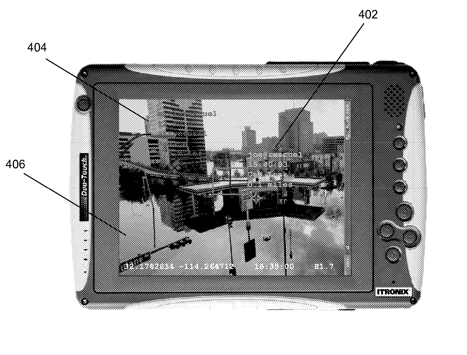
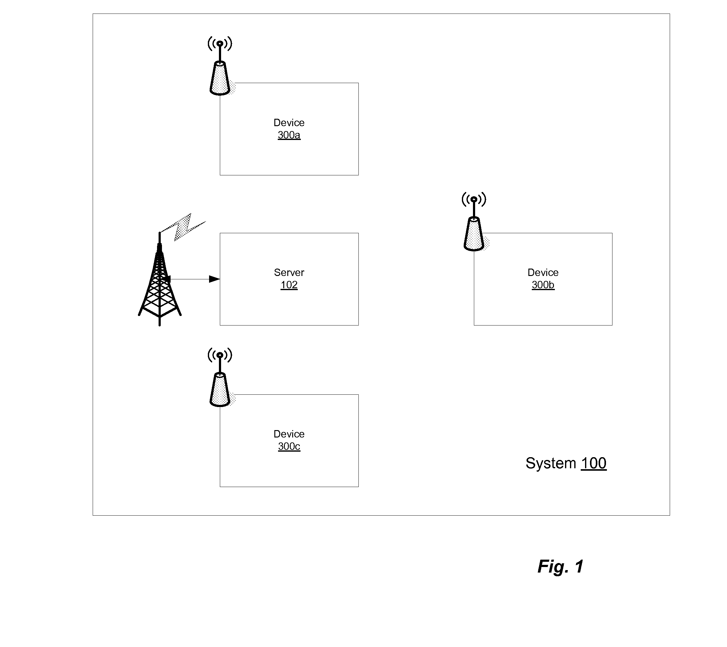
[0027]FIG. 1 illustrates a system 100 for providing wireless collaboration in accordance with an embodiment of the present invention. System 100 includes a server 102 and wireless client devices 300a, 300b, 300c. As illustrated, server 102 is in contact with client devices 300a, 300b and 300c via a wireless interface, for example a cellular network. Multiple client devices 300a, 300b, and 300c are illustrated to indicate that server 102 may be in contact with a plurality of client devices. For clarity of description, we refer generally to client device 300, though any number of client devices may be in operation and communication with server 102. The operation of and interaction between server 102 and client device 300 is described further below.

[0028] In one embodiment, geographically tagged messages are received and sent by client device 300 via its wireless network interface 310. Messages in one embodiment include latitude, longitude and elevation coordinates, and in one embodim...


PUM


Abstract

A wireless networked device incorporating a display, a video camera and a geo-location system receives geo-located data messages from a server system. Messages can be viewed by panning the device, revealing the message's real world location as icons and text overlaid on top of the camera input on the display. The user can reply to the message from her location, add data to an existing message at its original location, send new messages to other users of the system or place a message at a location for other users. World Wide Web geo-located data can be explored using the system's user interface as a browser. The server system uses the physical location of the receiving device to limit messages and data sent to each device according to range and filtering criteria, and can determine line of sight between the device and each actual message to simulate occlusion effects.

Description

CROSS-REFERENCE TO RELATED APPLICATIONS [0001] This application claims the benefit of U.S. Provisional Application Ser. No. 60 / 755,732, filed on Dec. 29, 2005, which is incorporated by reference herein in its entirety.BACKGROUND OF THE INVENTION [0002] 1. Field of the Invention [0003] The present invention relates generally to the field of computer graphics and networked wireless communication. [0004] 2. Description of the Related Art [0005] The World-Wide-Web, e-mail and instant messaging have revolutionized team collaboration, together with applications such as Lotus Notes and Microsoft Groove. The availability of mobile computing devices, together with access to the Global Positioning System (GPS) network are starting to bring the tools available for fixed location team collaboration to any place at any time. Devices such as the RIM Blackberry and the Palm Treo have brought e-mail to mobile devices with great success, but their effectiveness is certainly limited compared to the e...

Claims


Application Information

Patent Timeline
Patent Type & Authority Applications(United States)
IPC IPC(8): H04N7/14H04M3/42H04Q7/20H04W4/02H04W72/04
CPCH04L12/5865H04L51/20H04W4/02H04W8/24H04W64/006H04W4/185H04L67/36H04L67/14H04L67/18H04L67/148H04W92/18H04L51/222H04L67/52H04L67/75
Inventor SANZ-PASTOR, IGNACIOMORGAN, DAVID L. IIICASTELLAR, JAVIER
Owner AECHELON TECH
Why Eureka
Try Eureka