Speed- and User-Dependent Timbre and Dynamic Range Control Method, Apparatus and System for Automotive Audio Reproduction Systems

a dynamic range and control method technology, applied in tone control, transducer casings/cabinets/supports, electrical apparatus, etc., can solve the problems of phase response that has detrimental effects on the reproduced audio signal, degraded audio quality of traditional systems, and audible phase shift caused by these filters

Inactive Publication Date: 2007-10-18
BANG & OLUFSEN
View PDF7 Cites 15 Cited by
  • Summary
  • Abstract
  • Description
  • Claims
  • Application Information

AI Technical Summary

Benefits of technology

[0017] Based on the above background, it is the objective of the present invention to provide a method and corresponding devices and systems that do not suffer from or at least reduce said detrimental effects of traditional filters and wide-band level control.

Problems solved by technology

One problem associated with this implementation lies in the audibility of the phase shift caused by these filters.
For example, a minimum-phase implementation of a shelving filter has a characteristic phase response that has detrimental effects on the reproduced audio signal.
Thus, although the desired magnitude response is attained, the traditional system suffers from a degraded audio quality due to phase response artefacts such as an audible “ringing” effect.
The result is a control of the signal's level and dynamic range, however, this control is applied to all frequency bands in the signal, resulting in at least two possible unwanted artefacts: 1.

Method used


Image

  • Speed- and User-Dependent Timbre and Dynamic Range Control Method, Apparatus and System for Automotive Audio Reproduction Systems
  • Speed- and User-Dependent Timbre and Dynamic Range Control Method, Apparatus and System for Automotive Audio Reproduction Systems
  • Speed- and User-Dependent Timbre and Dynamic Range Control Method, Apparatus and System for Automotive Audio Reproduction Systems

Examples


Embodiment Construction

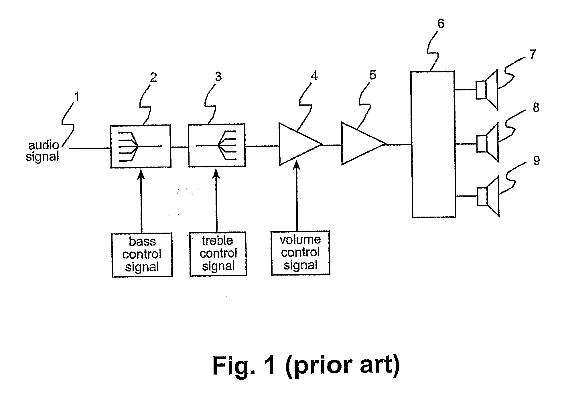
[0049] With reference to FIG. 1, there is shown a traditional timbre-adjustment device (tone control) of a type well-known within the field of audio reproduction techniques for driving a passive loudspeaker. An audio signal is provided at an input terminal 1 to a bass control unit 2 followed by a treble control unit 3. The characteristics of these control units are determined by gain parameters provided to the two shelving filters used in these control units. The gain characteristics are indicated in the units 2 and 3 in FIG. 1 in a schematic manner. The output signal from the treble control unit is provided to a power amplifier 5 via a gain control 4, controlling the overall gain of the system. The output of the power amplifier is connected to a frequency crossover network 6. The frequency band-limited output signals from the crossover device are individually connected to loudspeakers 7, 8, and 9.

[0050] As mentioned in the summary of the invention, a drawback of this implementatio...


PUM


Abstract

Typically, changes in timbre in an audio reproduction system use analogue or digital filters, either shelving filters (as in the case of bass, treble and loudness controllers) and/or peaking filters (as in the case of speed-and noise-compensation in automotive systems). A problem associated with this implementation lies in the audibility of the phase shift caused by these filters. According to the invention, this and further problems are solved by utilising the crossover network of the system itself—with level adjustable output signals—to attain desired timbre and/or dynamic range adjustments and hence avoiding undesirable phase effects of the traditional bass and treble control filters. An input signal (18) is according to an embodiment of the invention divided by a cross over network (20) into a number of frequency bands and applied via level control means (21, 22, 23) and separate power amplifiers (24, 25, 26) to loudspeaker drivers (27, 28, 29). In this manner, the mentioned phase shifts can be avoided and by proper control of the level adjustment means by a frequency-dependent analysis and weighting network (30), desired adjustment of timbre and dynamic range of the audio reproduction can be achieved. Also control dependent on vehicle speed and/or background noise can be incorporated into the system..

Description

TECHNICAL FIELD [0001] The present invention relates generally to methods, devices and systems for use in adjusting the timbre, dynamic range, and level of a reproduced audio signal and specifically to such methods, devices and systems used in automotive audio reproduction systems. BACKGROUND OF THE INVENTION [0002] Audio reproduction systems for automotive use traditionally have been equipped with systems that control the overall basic timbre and / or dynamic range of program material reproduced by the system. These systems can be user-controlled as exemplified in the following cases: [0003] 1. Bass level adjustment [0004] 2. Treble level adjustment [0005] 3. “Loudness” compensation (i.e. a frequency-dependent gain applied at low listening levels) [0006] Alternatively, they may be automatically adjusted as in the following examples: [0007] 1. Auto-loudness (i.e. a loudness function as described above that is invoked automatically by the system according to the user-determined listeni...

Claims


Application Information

Patent Timeline
Patent Type & Authority Applications(United States)
IPC IPC(8): H03G5/00
CPCH03G9/005H04R5/04H03G9/025
Inventor GLEN, GEOFFREY
Owner BANG & OLUFSEN
Why Eureka
Try Eureka