Thermal Processing System and Configurable Vertical Chamber

a vertical chamber and processing system technology, applied in the direction of superimposed coating process, liquid/solution decomposition chemical coating, resistive material coating, etc., can solve the problems of increasing processing time, occupying a tremendous amount of space and power, and considerable time required both before processing

Inactive Publication Date: 2007-10-18
DU BOIS DALE R +4
View PDF76 Cites 283 Cited by
  • Summary
  • Abstract
  • Description
  • Claims
  • Application Information

AI Technical Summary

Benefits of technology

[0023] According to yet another aspect of the invention, the apparatus further includes a liner separating the carrier from the top wall and the side wall of the process chamber, and a distributive or cross-flow injection system to direct flow of a fluid across surfaces of each of the substrates held in the carrier. The cross-flow injection system generally includes a cross-flow injector having a number of injection ports positioned relative to substrates held in the carrier, and through which the fluid is introduced on one side of the number of substrates. A number of exhaust ports in the liner positioned relative to the substrates held in the carrier cause the fluid to flow across the surfaces of the substrates. Fluids introduced by the cross-flow injection system can include process gas or vapor, and inert purge gases or vapor used for purging or backfilling the chamber or for cooling the substrates therein.

Problems solved by technology

This arrangement is undesirable since it entails a larger chamber volume that must be pumped down, filled with process gas or vapor, and backfilled or purged, resulting in increased processing time.
Moreover, this configuration takes up a tremendous amount of space and power due to a poor view factor of the wafers from the heaters.
Other problems with conventional thermal processing apparatuses include the considerable time required both before processing to ramp up the temperature of the process chamber and the wafer to be treated, and the time required after processing to ramp down the temperature.
Furthermore, additional time is often required to ensure the temperature of the process chamber has stabilized uniformly at the desired temperature before processing can begin.
Thus, the time required to quickly ramp up and / or down the temperature of the process chamber to a uniform temperature significantly limits the throughput of the conventional thermal processing apparatus.
However, this approach also increases the magnitude of the risk should something go wrong during processing.
That is a larger number of wafers could be destroyed or damaged by a single failure, for example, if there was an equipment or process failure during a single processing cycle.
Another problem with this solution is that increasing the size of the process chamber to accommodate a larger number of wafers increases the thermal mass effects of the process chamber, thereby reducing the rate at which the wafer can be heated or cooled.
Moreover, larger process chambers processing larger batches of wafers leads to or compounds a first-in-last-out syndrome in which the first wafers loaded into the chamber are also the last wafers removed, resulting in these wafers being exposed to elevated temperatures for longer periods and reducing uniformity across the batch of wafers.
Another problem with the above approach is that systems and apparatuses used for many of the processes before and after thermal processing are not amenable to simultaneous processing of large numbers of wafers.
Thus, thermal processing of large batches or large numbers wafers, while increasing the throughput of the thermal processing apparatus, can do little to improve the overall throughput of the semiconductor fabrication facility and may actually reduce it by requiring wafers to accumulate ahead of the thermal processing apparatus or causing wafers to bottleneck at other systems and apparatuses downstream therefrom.
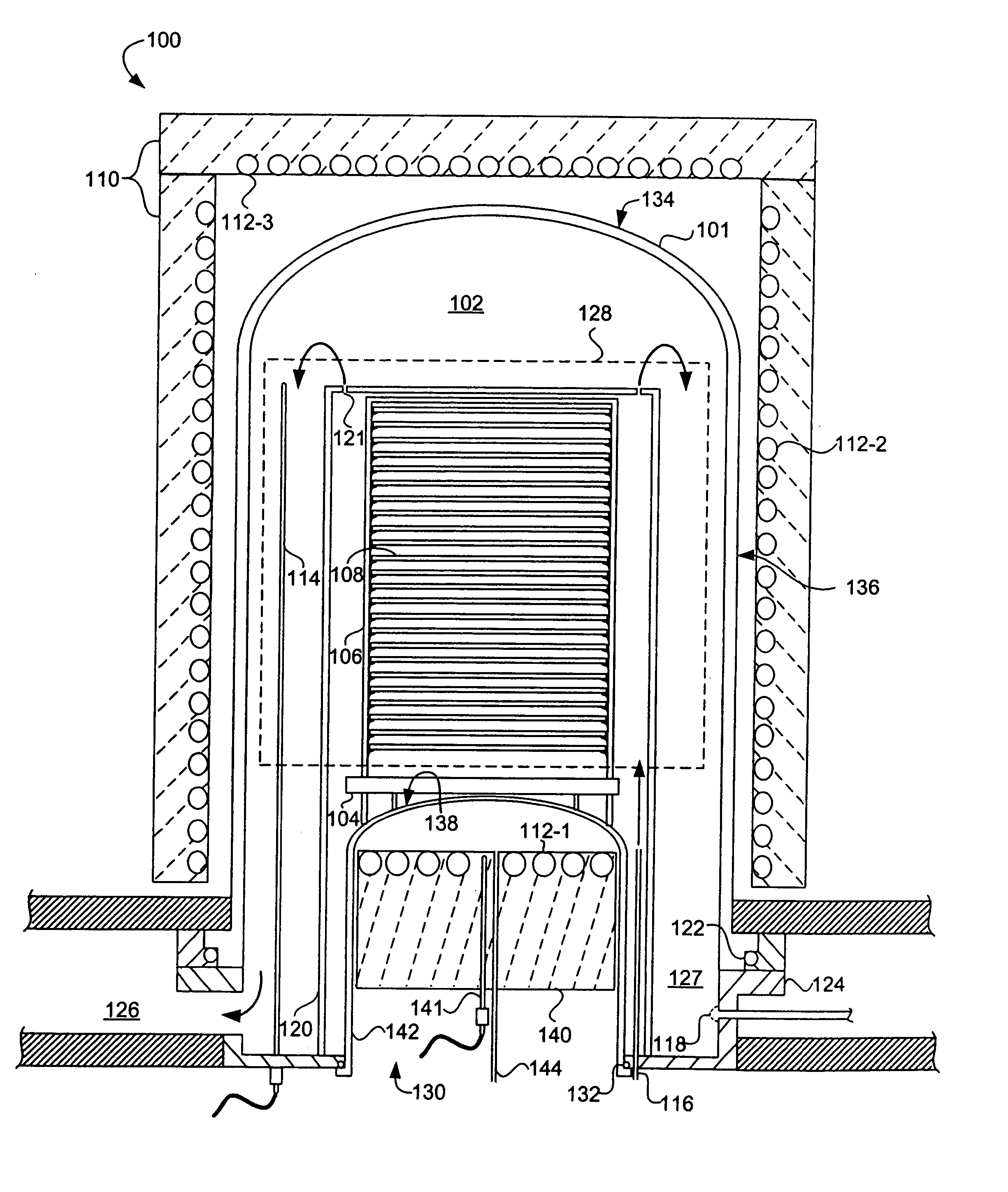
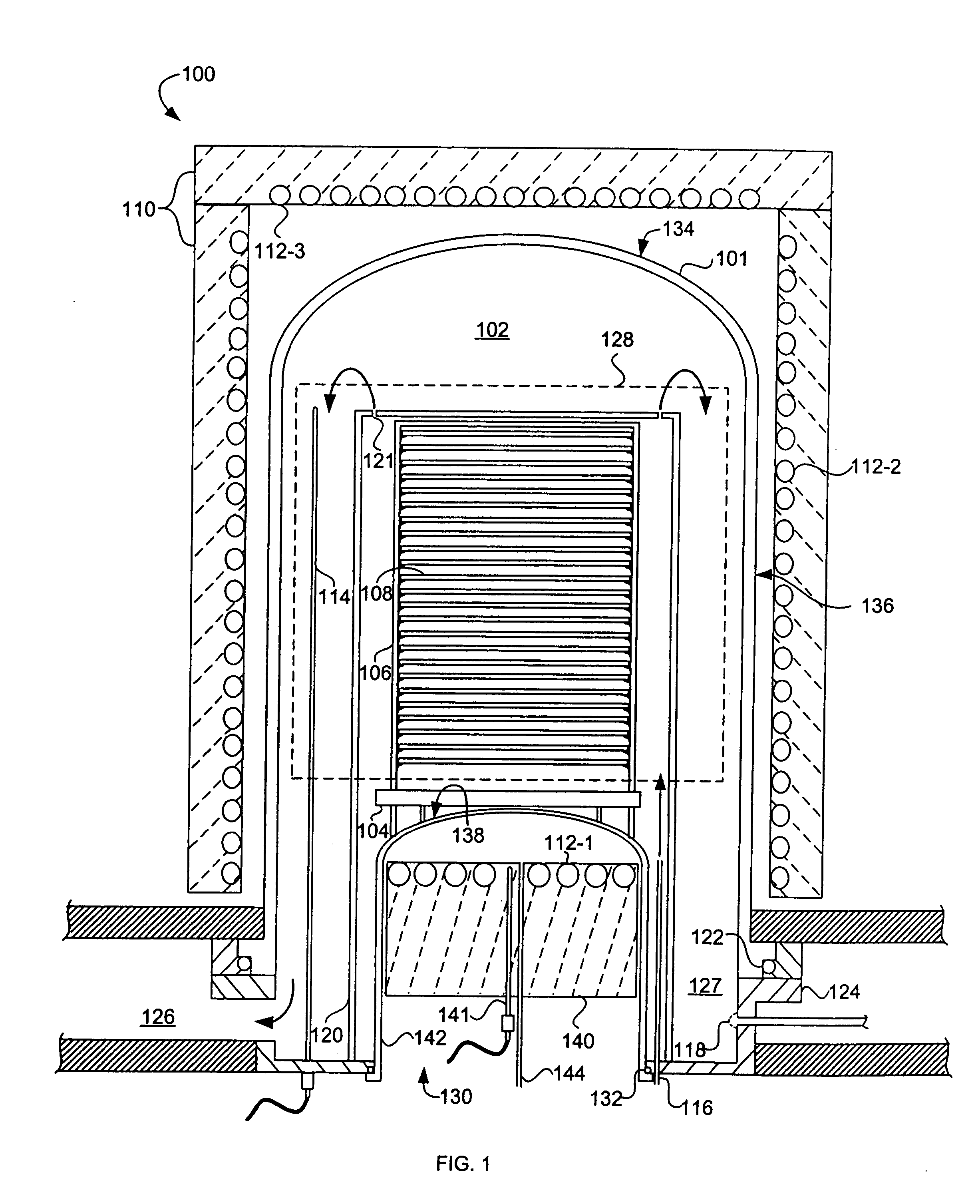
Unfortunately, conventional RTP systems have significant shortcomings including the placement of the lamps, which in the past were arranged in zones or banks each consisting of a number of lamps adjacent to sidewalls of the process chamber.
This configuration is problematic because it takes up a tremendous amount of space and power in order to be effective due to their poor view factor, all of which are at a premium in the latest generation of semiconductor processing equipment.
Another problem with conventional RTP systems is their inability to provide uniform temperature distribution across multiple wafers within a single batch of wafers and even across a single wafer.
There are several reasons for this non-uniform temperature distribution including (i) a poor view factor of one or more of the wafers by one or more of the lamps, and (ii) variation in output power from the lamps.
Moreover, failure or variation in the output of a single lamp can adversely affect the temperature distribution across the wafer.
However, the moving parts required to rotate the wafer, particularly the rotating feedthrough into the process chamber, adds to the cost and complexity of the system, and reduces the overall reliability thereof.
Yet another troublesome area for RTP systems is in maintaining uniform temperature distribution across the outer edges and the center of the wafer.
Most conventional RTP systems have no adequate means to adjust for this type of temperature non-uniformity.
As a result, transient temperature fluctuations occur across the surface of the wafer that can cause the formation of slip dislocations in the wafer at high temperatures, unless a black body susceptor is used that is larger in diameter than the wafer.
For example, there are no adequate means for providing uniform power distribution and temperature uniformity during transient periods, such as when the lamps are powered on and off, unless phase angle control is used which produces electrical noise.
Repeatability of performance is also usually a drawback of lamp-based systems, since each lamp tends to perform differently as it ages.
Replacing lamps can also be costly and time consuming, especially when one considers that a given lamp system may have upwards of 180 lamps.
The power requirement may also be costly, since the lamps may have a peak power consumption of about 250 kWatts.

Method used


Image

  • Thermal Processing System and Configurable Vertical Chamber
  • Thermal Processing System and Configurable Vertical Chamber
  • Thermal Processing System and Configurable Vertical Chamber

Examples


Embodiment Construction

[0044] The present invention is directed to an apparatus and method for processing a relatively small number or mini-batch of one or more work pieces, such as semiconductor substrates or wafers, held in a carrier, such as a cassette or boat, that provides reduced processing cycle times and improved process uniformity.

[0045] As used herein the term “mini-batch” means a number of wafers less than the hundreds of wafers found in the typical batch systems, and preferably in the range of from one to about fifty-three semiconductor wafers or wafers, of which from one to fifty are product wafers and the remainder are non-product wafers used for monitoring purposes and as baffle wafers.

[0046] By thermal processing it is meant processes that in which the work piece or wafer is heated to a desired temperature which is typically in the range of about 350° C. to 1300° C. Thermal processing of semiconductor wafers can include, for example, heat treating, annealing, diffusion or driving of dopa...


PUM

PropertyMeasurementUnit
temperatureaaaaaaaaaa
timeaaaaaaaaaa

Abstract

An apparatus (100) and method are provided for thermally processing substrates (108) held in a carrier (106). The apparatus (100) includes a vessel (101) having a top (134), side (136) and bottom (138), and a heat source (110) with heating elements (112-1, 112-2, 112-3) proximal thereto. The vessel (101) is sized to enclose a volume substantially no larger than necessary to accommodate the carrier (106), and to provide an isothermal process zone (128) extending throughout. In one embodiment, the bottom wall (138) includes a movable pedestal (140) with a bottom heating element therein (112-1), and the pedestal can be lowered and raised to insert the carrier (106) into the vessel (101). The apparatus (100) can include a movable shield (146) that is inserted between the pedestal (140) and the carrier (106) to shield the substrates (108) from the heating element (112-1) and to maintain pedestal temperature. A magnetically coupled repositioning system (162) repositions the carrier (106) during processing of the substrates (108) without use of a movable feedthrough into the volume enclosed by the vessel (101), and without moving the bottom heating element (112-1) in the pedestal (140).

Description

CROSS REFERENCE TO RELATED APPLICATIONS [0001] The present application claims the benefit of and priority from commonly assigned U.S. Provisional Patent Application Ser. Nos. 60 / 396,536, entitled Thermal Processing System, and filed Jul. 15, 2002, and 60 / 428,526, entitled Thermal Processing System and Method for Using the Same, and filed Nov. 22, 2002, both of which are incorporated herein by reference in their entirety.TECHNICAL FIELD [0002] The present invention relates generally to systems and methods for heat-treating objects, such as substrates. More specifically, the present invention relates to an apparatus and method for heat treating, annealing, and depositing layers of material on or removing layers of material from a semiconductor wafer or substrate. BACKGROUND [0003] Thermal processing apparatuses are commonly used in the manufacture of integrated circuits (ICs) or semiconductor devices from semiconductor substrates or wafers. Thermal processing of semiconductor wafers i...

Claims


Application Information

Patent Timeline
Patent Type & Authority Applications(United States)
IPC IPC(8): C23C16/00
CPCC23C16/4583H01L21/67757H01L21/67109C23C16/46
Inventor DU BOIS, DALE R.NAM, JAMIE H.WILDMAN, CRAIGQIU, TAIQUINGKOWALSKI, JEFFREY M.
Owner DU BOIS DALE R
Why Eureka
Try Eureka