
Eureka
For R&D, Eureka makes reading and utilizing patents & technical documents easy.
Eureka AIR
Designed for self-driven R&D workflows. Generate viable solutions, solve complex R&D challenges, empower your innovation with AI.

Eureka Materials
Designed for material experts only. Revolutionize your material R&D, from search, analyze, to developing new materials.

TechResearch
Generate reliable direction feasibility study reports for your R&D in just a few steps.

TechSeek
Discover and master advanced knowledge NOW. Basics, ideas, possibilities, all at once.

TechMind
As an expert in R&D Theories, TechMind can generates customized viable solutions instantly.

TechRisk
Analyze your overall solution with one click, know your potential R&D risks in advance.

TechMonitor
Get weekly tech updates, stay abreast of the latest tech innovations and key insights.
Methods of Making Flash Memory Cell Arrays Having Dual Control Gates Per Memory Cell Charge Storage Element
- Summary
- Abstract
- Description
- Claims
- Application Information
AI Technical Summary
Benefits of technology
Problems solved by technology
Method used
Image

Examples
embodiment 1
Alternate Embodiment 1
Use of Spacers To Define The Floating Gate Channel Length
[0083] This embodiment, like the Second NAND Array Embodiment, uses spacers to define the channel length of the floating gates. FIG. 17A is a plan view showing a set of photoresist strips of width W′ and pitch P running horizontally in the X direction. FIG. 17B is a cross section through section A-A of FIG. 17A and shows a collection of layers underlying the photoresist strips 1711. Referring to FIG. 17B, a substrate 1700 is appropriately doped to contain one or more wells and a layer of tunnel dielectric 1702 is grown or formed by deposition over a surface 1701 of the substrate, typically to a thickness in the range of 5 nm to 10 nm. A layer of polysilicon 1705 having a thickness in the range of 30 to 80 nm is then deposited over dielectric 1702, an oxide pad 1708 is thermally grown or deposited on its top surface, and a nitride layer 1709 is deposited over the oxide pad forming a composite dielectric l...
embodiment 2
Alternate Embodiment 2
Partially Submerged Floating Gate
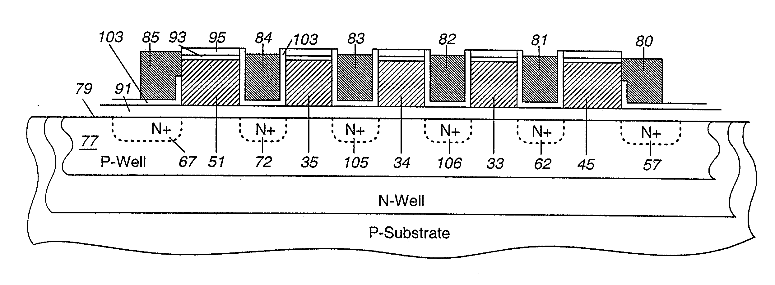
[0097] This embodiment is similar to the First NAND Array Embodiment in that direct photolithography rather than spacer technology is used to define the array. However, it differs from the First NAND Array Embodiment in that the floating gate is partially submerged below the original silicon surface 1701 (FIG. 17B) or 1901 (FIG. 19B). The process flow is similar to that described in Alternate Embodiment 1 (FIG. 17) except an additional sequence of steps is added at the beginning to allow the floating gate to be submerged, and the steps associated with spacers are removed. FIG. 19A shows a plan view of the completed structure corresponding to FIG. 17N, and FIG. 19B shows a cross section along section A-A of FIG. 19A.
[0098] The process begins by growing a thin sacrificial thermal oxide followed by a silicon nitride deposition over a silicon substrate 1900 containing appropriate well regions and having surface 1901. The thickness...
embodiment 3
Alternate Embodiment 3
Partially Submerged Floating Gate Formed Using Spacer Technology
[0099] In another embodiment the partially submerged floating gate structure can be formed using spacer technology. The process is very similar to that described earlier with respect to FIG. 19. Referring to FIG. 20A, a sacrificial oxide 2004 is grown over surface 2001 of silicon substrate 2000 followed by a deposition of silicon nitride. The nitride is patterned and etched into horizontal strips as in Alternate Embodiment 1 using standard photolithography, shown in cross section as 2006. Oxide spacer material 2008 is then deposited and etched back to the top surface of the nitride. A second layer of nitride 2009 is deposited completing the structure shown in FIG. 20A. This structure is then etched back using the oxide spacer material and the sacrificial oxide as an etch stop, leaving not only the original regions of nitride 2006 but also nitride regions 2006a in the area between the oxide spacers...
PUM
 Abstract
Description
Claims
Application Information
 - R&D Engineer
- R&D Manager
- IP Professional
- Industry Leading Data Capabilities
- Powerful AI technology
- Patent DNA Extraction
Browse by: Latest US Patents, China's latest patents, Technical Efficacy Thesaurus, Application Domain, Technology Topic, Popular Technical Reports.
© 2024 PatSnap. All rights reserved.Legal|Privacy policy|Modern Slavery Act Transparency Statement|Sitemap|About US| Contact US: help@patsnap.com