Automatic roof ventilation system

a technology of automatic ventilation and roof ventilation, which is applied in ventilation systems, lighting and heating apparatus, heating types, etc., can solve the problems of r value stealing, most common energy loss in a home, and passive ventilation system not teaching camouflaged active ventilation system, etc., to achieve the effect of minimal energy consumption

Inactive Publication Date: 2007-10-18
OHAGIN CAROLINA
View PDF21 Cites 83 Cited by
  • Summary
  • Abstract
  • Description
  • Claims
  • Application Information

AI Technical Summary

Benefits of technology

[0008]Preferred embodiments of the present invention provide a roof ventilation system which is operable based on varying environmental conditions with minimal energy consumption. In accordance with a preferred embodiment, a roof ventilation system is provided for a sloped roof having a ridge and an eave. The system comprises a first plurality of vents arranged generally linearly and positioned within the roof proximate one of the ridge and the eave. Each of the vents comprises a vent member comprising an opening that permits airflow between regions above and below the roof; and a fan configured to generate an air flow through the opening. In addition, the ventilation system includes a controller in communication with the fans of the vents. The controller is configured to drive the fans based on at least one environmental parameter.

Problems solved by technology

One of the most common energy losses in a home is due to heat transfer through the attic.
In colder climates, moisture builds up in the attic, robbing the insulation of much of its R value.
However, this passive ventilation system does not teach a camouflaged active ventilation system.
These grid-powered active ventilation systems require increased operation and installation costs compared with passive systems.
In the southwest, many homes have low pitch, hip roofs which have no gables, and dormers may destroy the aesthetics of a design if improperly located or too numerous.
Therefore, these systems have proven to be inadequate.

Method used


Image

  • Automatic roof ventilation system
  • Automatic roof ventilation system
  • Automatic roof ventilation system

Examples


Embodiment Construction

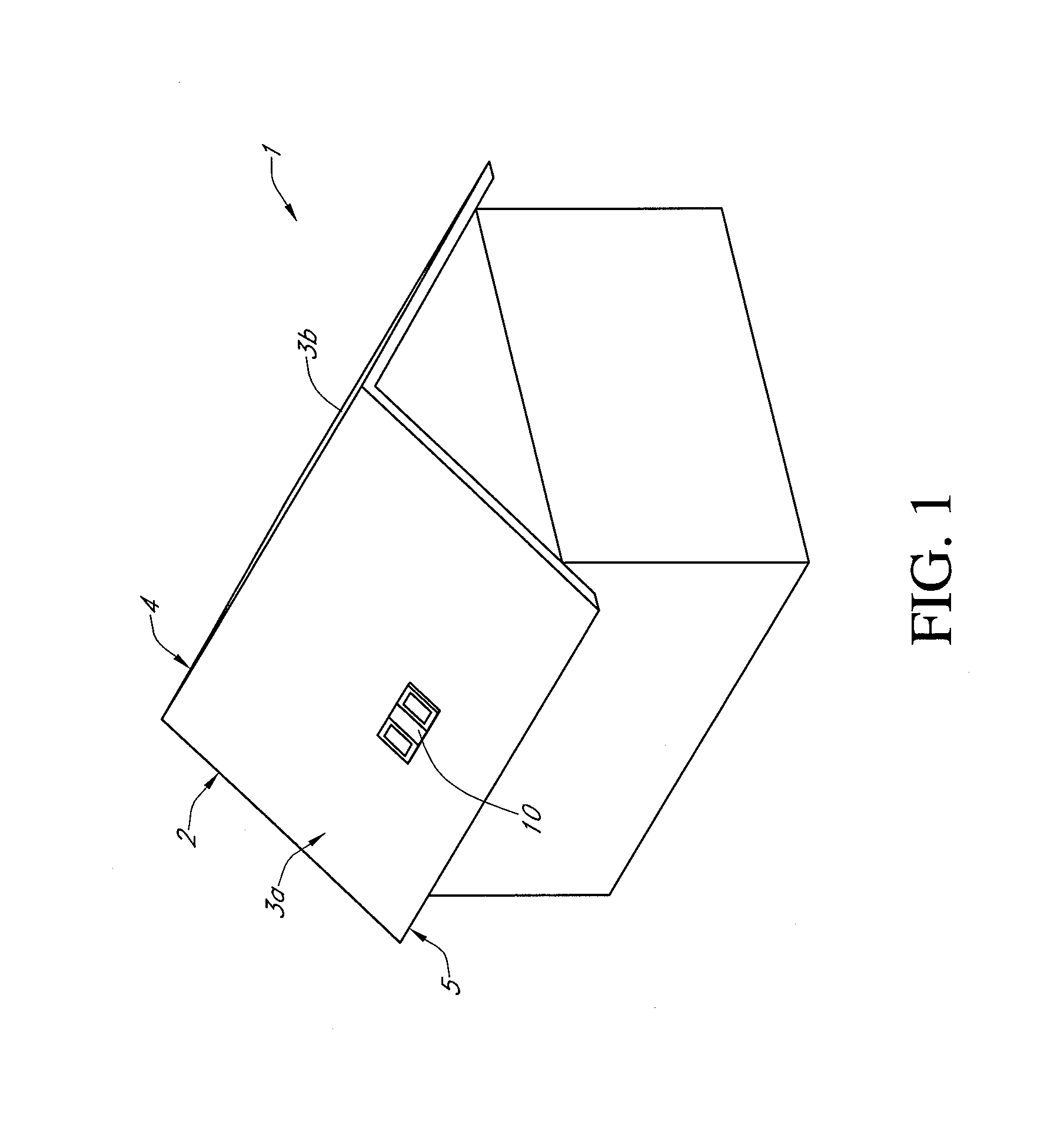
[0022]FIG. 1 shows a building 1 with a roof 2 comprising two fields 3a and 3b that are joined at their upper ends to define a ridge 4. Lower edges 5 of the fields are referred to as an “eave.” The fields 3a and 3b typically comprise a roof deck covered with roof cover elements such as tiles (e.g., clay or concrete), shingles (e.g., wooden, clay, or composition), or sheeting (e.g., metal). The illustrated roof is suitable for having one or more vents 10 according to one embodiment of the invention. Also, skilled artisans will appreciate that the vents may be provided in a wide variety of different types of roofs, including those not having ridges or sloped fields. In FIG. 1, the vent 10 is positioned on the central part of the field 3a. In other embodiments, the vent may be positioned on a different part of the field, depending on the ventilation needs.

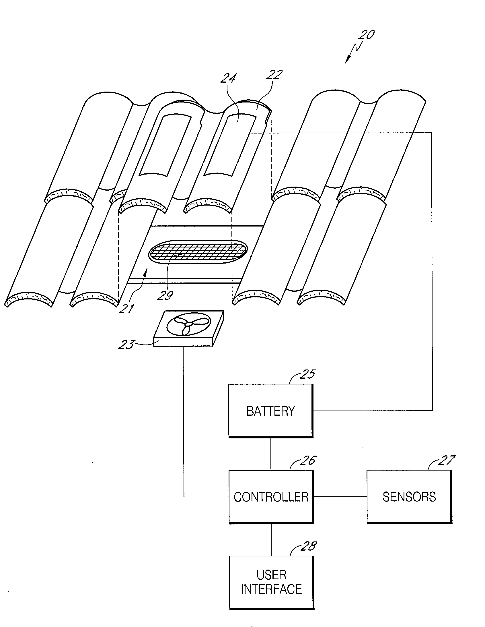
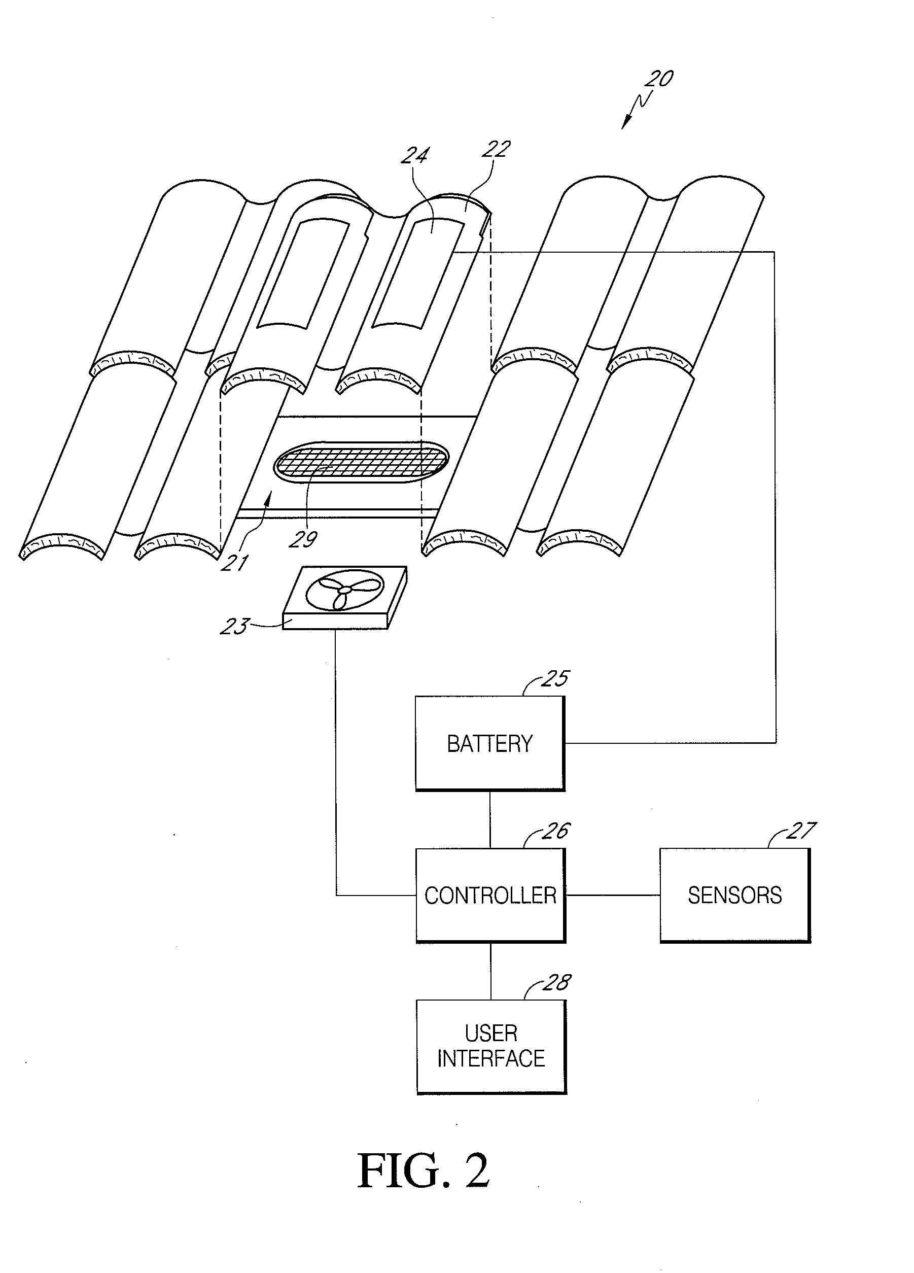
[0023]FIG. 2 illustrates one embodiment of a roof ventilation system 20. The illustrated ventilation system 20 is positioned within a...


PUM


Abstract

A roof ventilation system operable based on environmental parameters is disclosed. The system includes a vent, a fan, a solar panel, a battery and a controller. The vent is positioned within a field of a roof, and includes a first opening configured to allow airflow between regions above and below the roof. The fan is positioned to generate an air flow through the vent. The solar panel is positioned on the roof in a location such that the solar panel receives solar radiation. The battery is electrically connected to the solar panel. The controller is in communication with the fan, and is configured to drive the fan based on at least one environmental parameter.

Description

CLAIM FOR PRIORITY[0001]This application claims the priority benefit under 35 U.S.C. §119(e) of Provisional Application Ser. No. 60 / 793,337, filed Apr. 18, 2006. The full disclosure of this priority application is incorporated herein by reference.BACKGROUND OF THE INVENTION[0002]1. Field of the Invention[0003]This application relates generally to building ventilation and specifically to roof ventilation.[0004]2. Description of the Related Art[0005]Energy efficiency is a serious consideration in new home design. New homes require ways to minimize energy requirements to maintain comfortable living spaces. One of the most common energy losses in a home is due to heat transfer through the attic. In warm climates, heat builds up in the attic from solar energy incident on the roof. In colder climates, moisture builds up in the attic, robbing the insulation of much of its R value. Early efforts at minimizing the effects of heat and / or moisture build-up focused on insulation between the liv...

Claims


Application Information

Patent Timeline
Patent Type & Authority Applications(United States)
IPC IPC(8): F24F7/02
CPCF24F7/025F24F11/0001F24F11/001Y02B10/24F24F2005/0067Y02B10/20F24F11/0012F24F2005/0064F24F11/30F24F2110/00F24F2110/10Y02A30/272F24F11/77F24F11/65
Inventor O'HAGIN, CAROLINA
Owner OHAGIN CAROLINA
Why Eureka
Try Eureka