


Quick Research
Generate reliable direction feasibility study reports for your R&D in just a few steps.

Technical Q&A
Discover and master advanced knowledge NOW. Basics, ideas, possibilities, all at once.

Find Solutions
As an expert in R&D theories, this can generate solutions to your technical problems instantly.

Evaluate Feasibility
Analyze your overall solution with one click, know your potential R&D risks in advance.

Monitor Landscape
Get weekly tech updates, stay abreast of the latest tech innovations and key insights.
Heating/cooling system for indwelling heat exchange catheter
a heat exchange catheter and cooling system technology, applied in the field of heat exchange catheters and indwelling heat exchange catheters, can solve the problems that single-purpose heat exchange catheters, calif., and calif. can be less optimally used
- Summary
- Abstract
- Description
- Claims
- Application Information
AI Technical Summary
Benefits of technology
Problems solved by technology
Method used
Image

Examples
Embodiment Construction
Description of the Heating / Cooling System
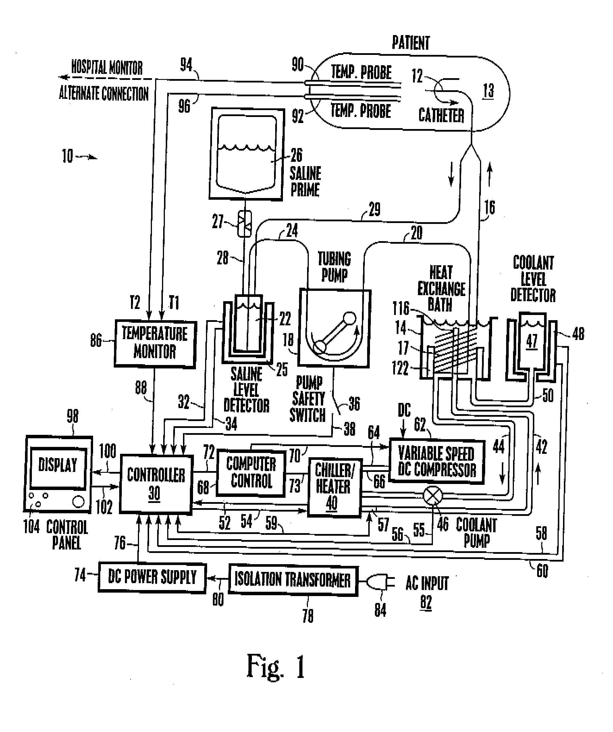
[0037] Referring initially to FIG. 1, a patient heating / cooling system is shown and generally designated 10. As shown, the system 10 includes three separate fluid circuits: a saline circuit (also referred to as the working fluid circuit), a water glycol circuit (also referred to as the heating / cooling fluid circuit), and a refrigerant circuit (also referred to as the refrigerating fluid circuit.)
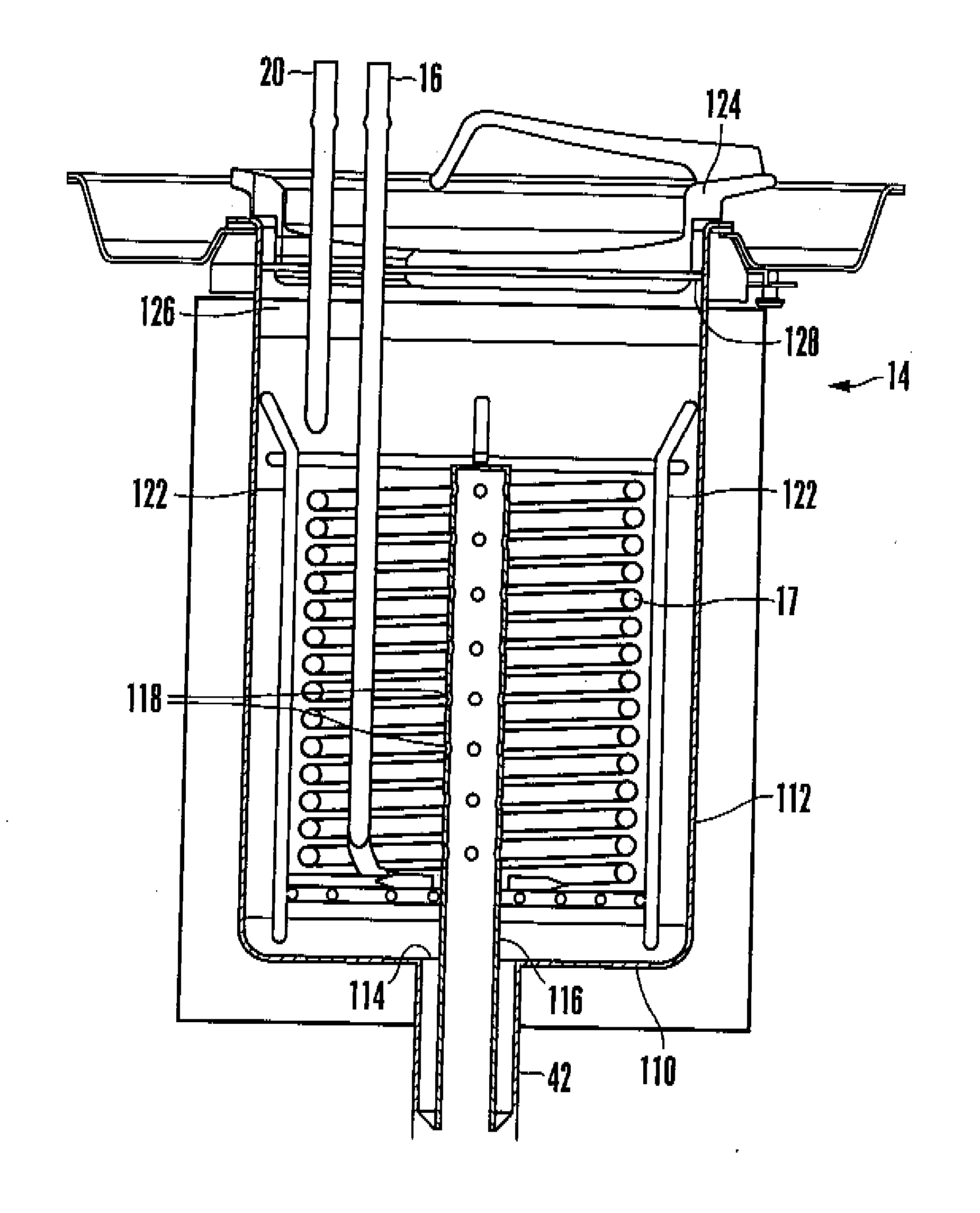
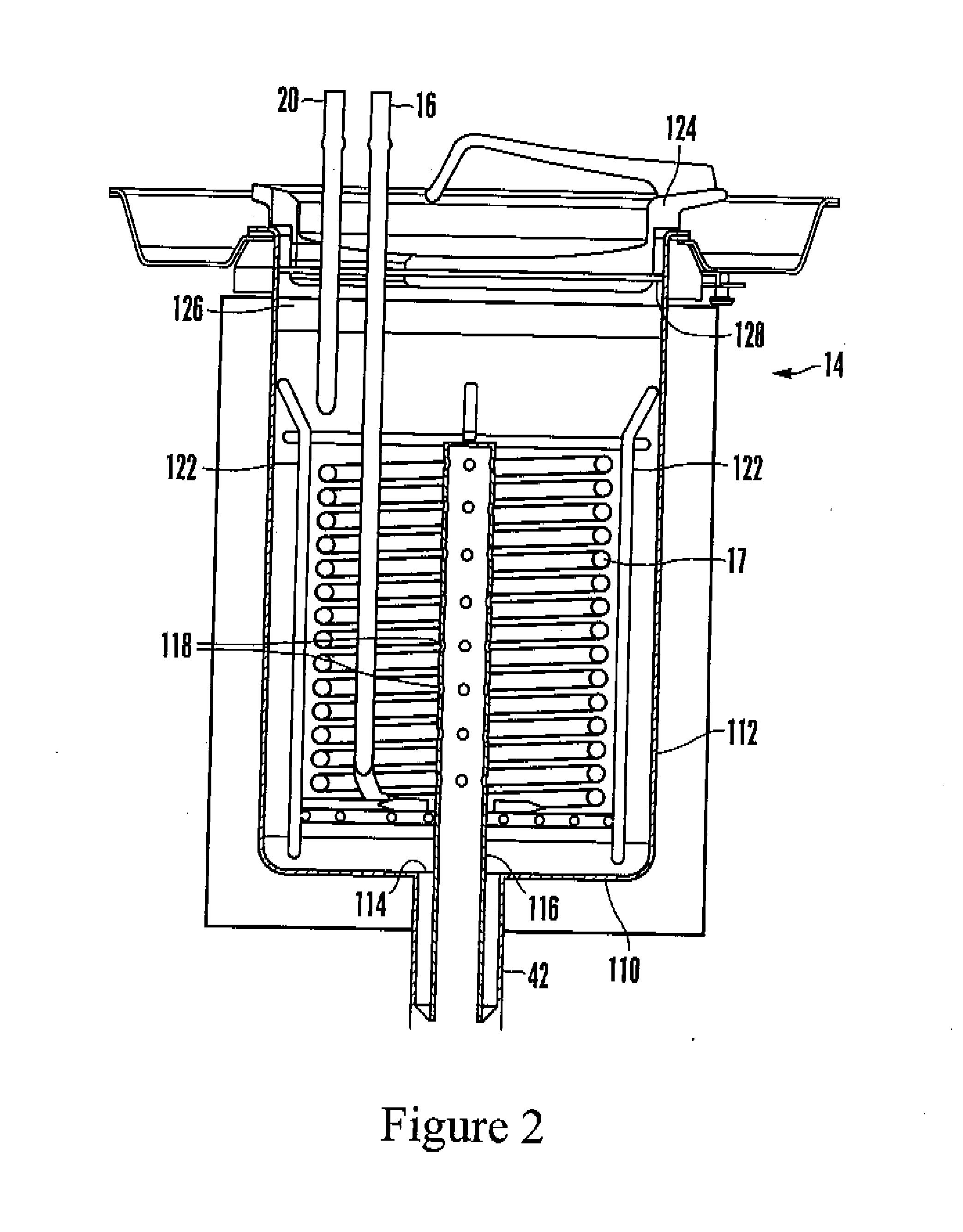
[0038] Taking the saline circuit first, an indwelling heat exchange catheter 12 that can be inserted into a patient 13 during an operation is connected to a heat exchange bath 14 by a saline supply line 16. The supply line 16 is connected to a coiled or helical heat exchange tube 17 that is immersed in the bath 14 fluid to exchange heat therewith. In turn, the heat exchange tube 17 is connected to a peristaltic tubing saline pump 18 by fluid line 20. Preferably, the saline pump 18 draws saline from a saline reservoir 22 via fluid line 24. As shown,...
PUM
 Abstract
Description
Claims
Application Information
 - R&D Engineer
- R&D Manager
- IP Professional
- Industry Leading Data Capabilities
- Powerful AI technology
- Patent DNA Extraction
Browse by: Latest US Patents, China's latest patents, Technical Efficacy Thesaurus, Application Domain, Technology Topic, Popular Technical Reports.
© 2024 PatSnap. All rights reserved.Legal|Privacy policy|Modern Slavery Act Transparency Statement|Sitemap|About US| Contact US: help@patsnap.com