Rod pushing and pulling machine

Inactive Publication Date: 2007-10-25
EARTH TOOL L L C
View PDF3 Cites 4 Cited by
  • Summary
  • Abstract
  • Description
  • Claims
  • Application Information

AI Technical Summary

Benefits of technology

[0006] Optionally, a spinner is mounted on the housing behind the bungee vise. The spinner includes a drive wheel and a motor connect to actuate the drive wheel, the drive wheel being positioned to engage an endmost rod of the rod string and couple or uncouple it from the rod string depending on the direction of rotation of the drive wheel. The spinner may include a torque vise positioned to engage the last rod of the rod string and “break” the joint (unthread the last rod part way)

Problems solved by technology

This reduces the size and cost of th

Method used


Image

  • Rod pushing and pulling machine
  • Rod pushing and pulling machine
  • Rod pushing and pulling machine

Examples


Embodiment Construction

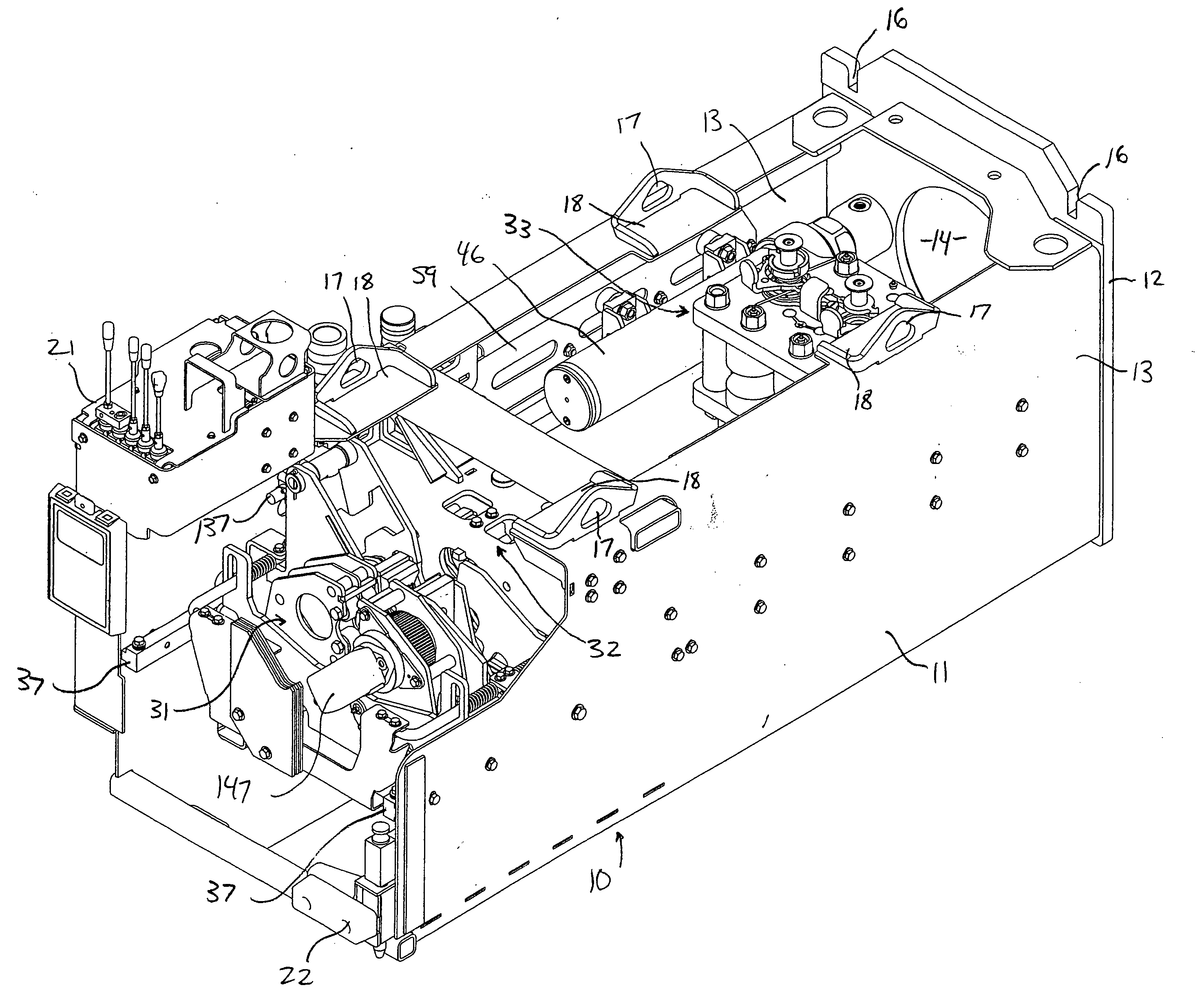
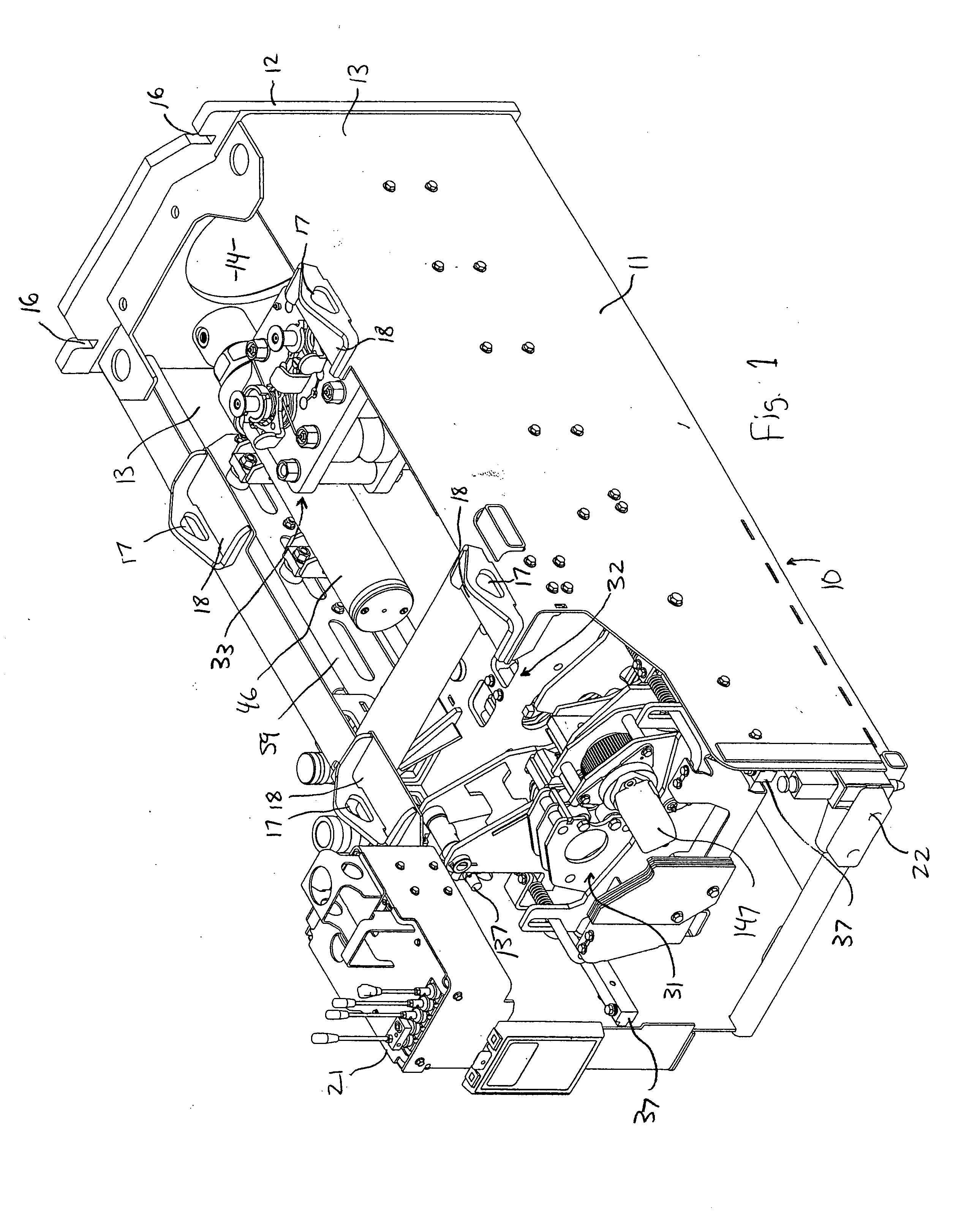
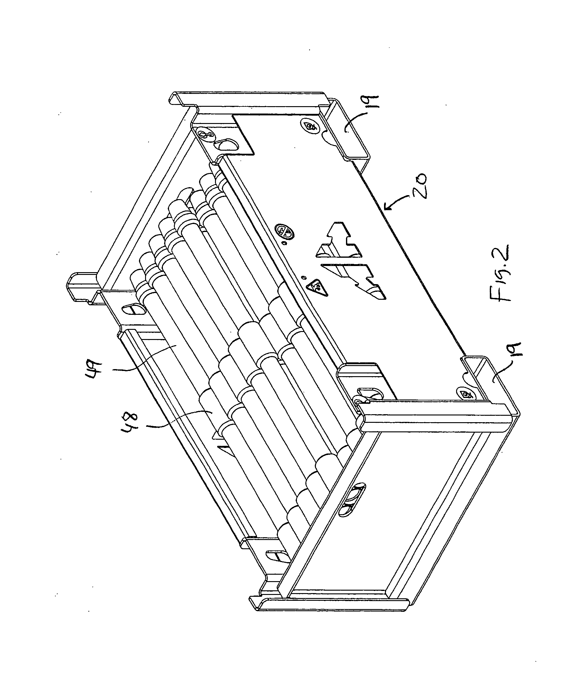
[0051] Referring now to FIGS. 1-3, a pipe pulling and pushing machine 10 according to the invention includes a hull 11 comprising a weldment including a front shore plate 12 and pair of side walls 13. Front shore plate 12 has a large centrally located hole 14 used for clearance to pull in tooling at the completion of the burst job. Front shore plate 12 has notches 16 in its upper edge that allow mounting of a second, removable shore plate. Sets of front and rear eyes 17 are provided on hull 11 for lifting machine 10 into and out of an access pit. Eyes 17 are formed in upturned flanges of four brackets 18 that receive the feet 19 of a rod storage box 20 therein. Operation of machine 10 is accomplished from a control station 21 mounted on an upper rear corner of hull 11. One component controlled from control station 21 is a hydraulic motor 147 described further below which provides torque to thread or unthread the rod joints. An optional L-shaped foot 22 is provided at the right rear ...


PUM


Abstract

The invention relates to an improved rod pushing and pulling machine suited for use in underground pipe bursting and replacement with a rod string wherein each rod has at least one radially enlarged upset thereon. The machine includes a housing or frame having a pair of side walls and a front wall with an access opening therein through which a rod string can extend. At least one main thrust cylinder is mounted on the housing. A ratchet block mechanism driven by the main thrust cylinder includes a pivoting pawl and a reversible stop mechanism that permits the pawl to swing out of the way of an upset on a rod as the ratchet block mechanism moves along the rod in one direction, but forces the pawl to engage the upset to drive the rod string when the ratchet block mechanism moves along the rod in the other direction. A bungee vise is mounted on the housing behind the ratchet block mechanism, the bungee vise having a pair of jaws and an actuator that causes the jaws to engage the rod string and hold it against longitudinal movement when the rod string is not engaged by the ratchet block mechanism, and disengage when the rod string is engaged by the ratchet block mechanism.

Description

TECHNICAL FIELD [0001] The invention relates to underground pipe bursting and replacement systems of the static type which operate by pushing or pulling a string of rods to which a bursting head or other tooling is attached. BACKGROUND OF THE INVENTION [0002] Pipe bursting is a well known process that brings enormous potential for the efficient and unobtrusive replacement of buried pipelines. Static bursting systems have been used for that purpose. Such systems pull or push a string of rods through the ground or existing pipeline. See for example Handford U.S. Pat. No. 5,205,671. Such systems generally provide a mechanism for both pulling / pushing the rod string and for adding and removing sections of rod to the end of the string. Most commonly, the rod strings used by these machines are made from consecutive cylindrical steel rods that are threaded together end to end as the rod string advances through the ground. Spinner mechanisms used to thread and unthread rods are known in the ...

Claims


Application Information

Patent Timeline
IPC IPC(8): B60B33/00
CPCE21B19/086Y10T16/212F16L55/1658E21B19/163
Inventor WENTWORTH, STEVEN W.CRANE, ROBERT F.
Owner EARTH TOOL L L C
Why Eureka
Try Eureka