Plastic aerosol container and method of manufacturing same

a technology of aerosol containers and aerosols, which is applied in the field of containers, can solve the problems of prone to internal corrosion, prone to rust, and prone to becoming easily damaged

Active Publication Date: 2007-10-25
SOUTHERN STAR CORP
View PDF10 Cites 59 Cited by
  • Summary
  • Abstract
  • Description
  • Claims
  • Application Information

AI Technical Summary

Benefits of technology

[0023] Preferably, the dispensing valve further includes a seal, formed of rubber or like material, positioned intermediate said neck and said flange, to prevent leakage of said product.
[0026] Also preferably, the container incorporates at least one strengthening rib therearound to provide structural rigidity to the container.
[0036] Preferably, said neck is tapered outwardly, such that, when the extremity of the neck is cut, it acts to assist in the snap-fitting of said collar thereto.

Problems solved by technology

They are prone to rust when in contact with water and are prone to internal corrosion unless provided with an appropriate coating which is compatible with the product to be dispensed or the formulations to be dispensed are prepared in such a way as to prevent corrosion.
In use, they are liable to become easily damaged, and / or, damage a substrate surface if they may be accidentally dropped thereon.
This is particularly a problem when such containers are commonly used in household applications, and can be easily dropped on tiled surfaces, which may then be easily chipped or damaged.
The deficiencies of such prior art metal containers have resulted in some relatively unsuccessful efforts to replace the metal container with a container formed of plastics.
The drawback of using such an arrangement is that, prior to supply of the product to be dispensed within the container body, the metal collar is required to be carefully placed to rest about the neck.
As the container is transported to the packaging plant and / or along the assembly line for supply of a product thereinto, the metal collar is prone to be very easily bumped from its desired position, with the consequence that the valve device cannot then be properly attached thereto.

Method used


Image

  • Plastic aerosol container and method of manufacturing same
  • Plastic aerosol container and method of manufacturing same
  • Plastic aerosol container and method of manufacturing same

Examples


Embodiment Construction

[0072] Throughout the drawings, like numerals will be used to identify similar features, except where expressly otherwise indicated.

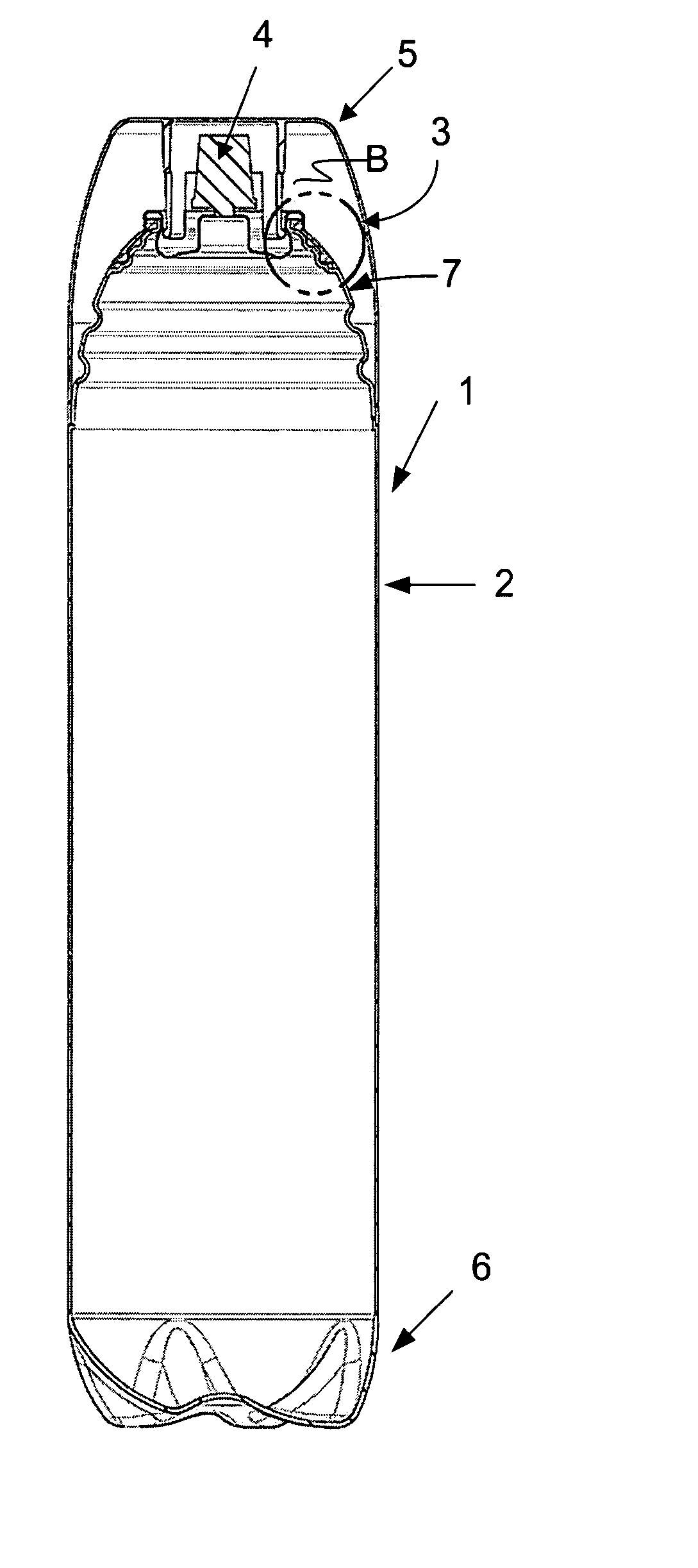
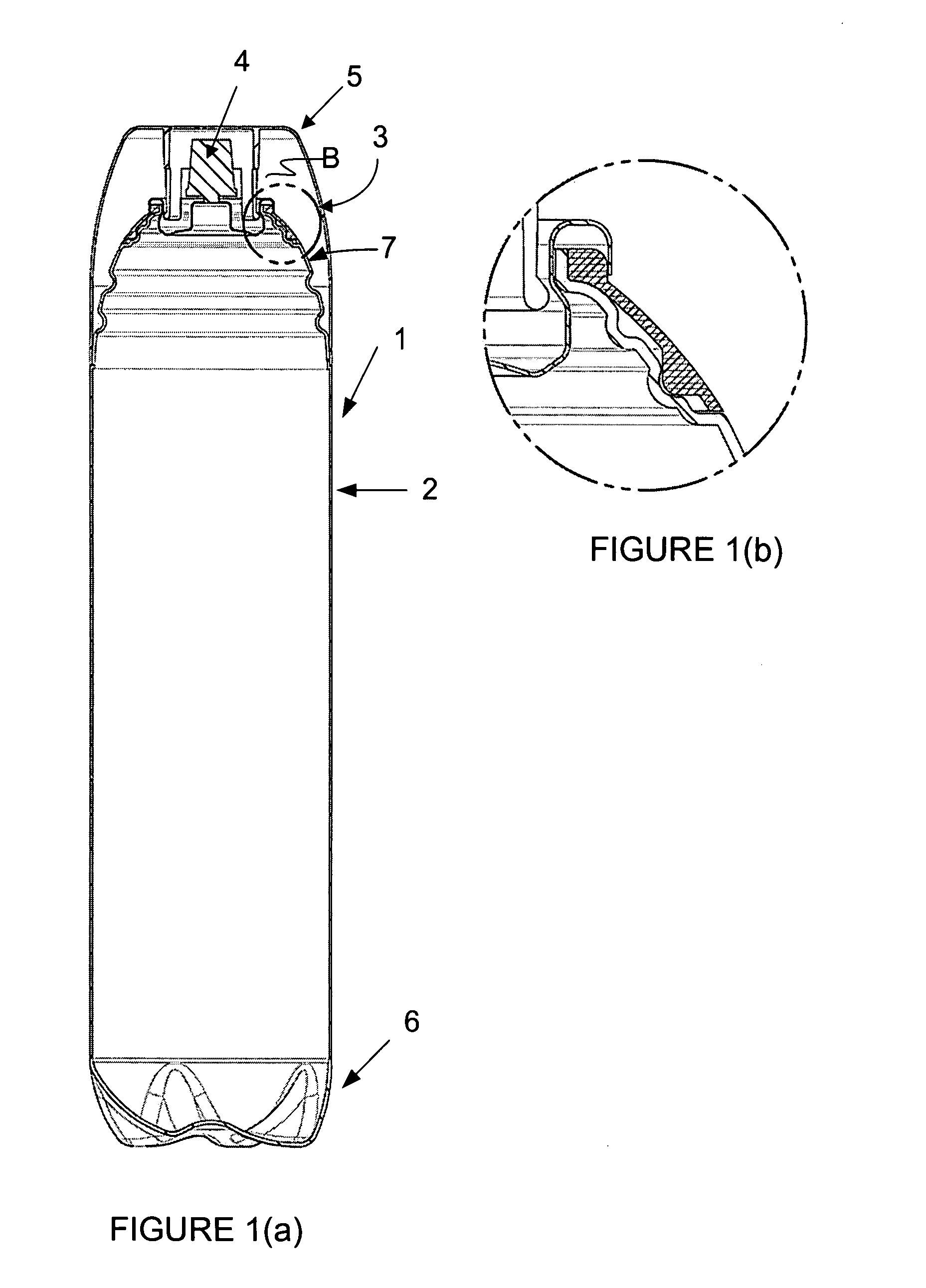
[0073] As shown in FIG. 1, a container, generally designated by the numeral 1, is formed of plastics material and has a body portion 2, a collar 3, a valving mechanism 4, and a cap or closure 5.

[0074] The body portion 2 is formed to have a base 6 at a first end thereof, and a neck portion 7 at a second end thereof. The body 2, including its base and neck portion, are all integrally formed by stretch blow moulding plastics material, such as polyethylene terephthalate (PET) from a preform, such as shown in FIG. 8.

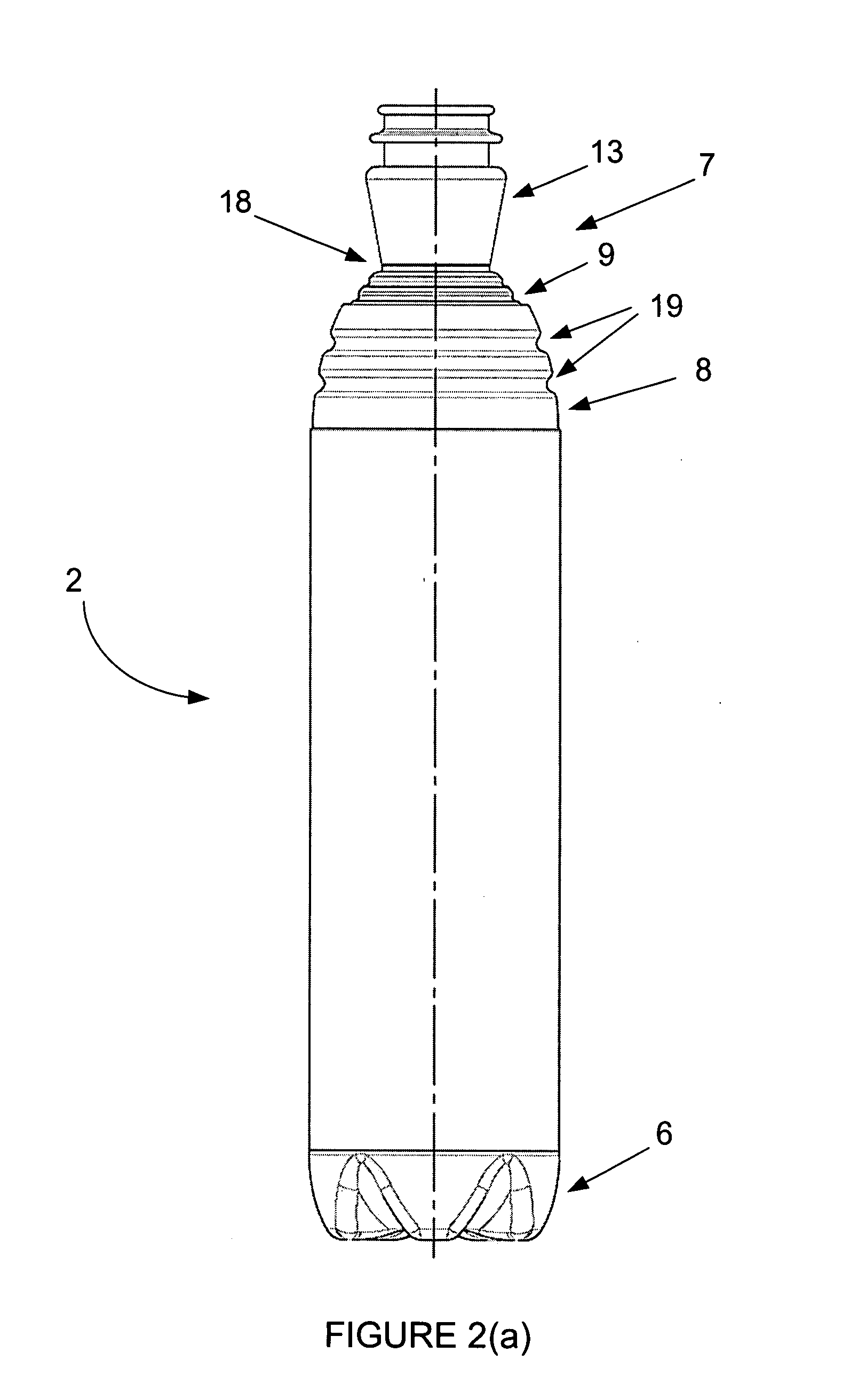
[0075]FIG. 2(a) shows the container after blow moulding but before the neck is trimmed, whilst FIG. 2(b) shows the same container after the neck is trimmed. It will be noted from the elevational view of the body portion 2, illustrated in FIG. 2, that the upper or neck portion 7 of the body of the container is formed having various discrete fea...


PUM

PropertyMeasurementUnit
diameteraaaaaaaaaa
structural rigidityaaaaaaaaaa
lengthaaaaaaaaaa

Abstract

A container (1) for dispensing a pressurised product and a method for manufacturing the container. The container (1) includes a body (2), a collar (3) and a dispensing valve (4). The body (2) is moulded from PET or like plastics, and has a shaped neck (7) surrounding an opening. The collar (3) is also moulded of plastics material, and is shaped to be snap-fitted to the shaped neck (7) of the body (2). Alternatively, the collar (3) is shaped to straddle the internal and external walls of the neck (7) of the body (2) to form a shaped lip therearound. The dispensing valve (4) is attached to the neck / collar (7,3), and has an outer flange (11) which is formed of malleable material and is shaped to fit about and be retained by the collar (3).

Description

BACKGROUND OF THE INVENTION [0001] The present invention relates to a container formed of plastics material, preferably PET, and which is adapted to dispense pressurised or aerosol products. The present invention also relates to a method of manufacturing such a container. DESCRIPTION OF THE PRIOR ART [0002] The reference in this specification to any prior publication (or information derived from it), or to any matter which is known, is not, and should not be taken as, an acknowledgement or admission or any form of suggestion that that prior publication (or information derived from it) or known matter forms part of the common general knowledge in the field of endeavour to which this specification relates. [0003] Containers for dispensing pressurised products have been, to date, primarily constructed of metal. In particular, a metal body, of substantially cylindrical shape, is formed having a seam along its length. Metal end closures, one having a manually actuable valve device, are a...

Claims


Application Information

Patent Timeline
Patent Type & Authority Applications(United States)
IPC IPC(8): B23P11/02B65D83/00B29C49/00B29C49/06B29C49/08
CPCB29C49/06B29C49/08B29C49/4278B29C65/58Y10T29/49876B29C2793/009B29K2067/00B65D83/38B29C66/5344B29C2791/001B29C66/71B29C66/612B29C66/12461B29C66/12441B29C66/1222B29C66/131B29C66/1224B29C66/135B29C2049/023B29K2067/003
Inventor SALAMEH, ASIM
Owner SOUTHERN STAR CORP
Why Eureka
Try Eureka