Soft impact, rotating jaw animal trap

a technology of rotating jaw and animal trap, which is applied in the field of soft impact and rotating jaw animal trap, can solve the problems of not being able to address two specific problems, not being able to solve the problem of long-term operation of capturing and holding animals, and not being able to solve the problem of reducing the likelihood of impact damage to the animal, reducing the likelihood of circulation, and increasing the holding power

Inactive Publication Date: 2007-10-25
PEDERSEN LARRY EDWARD +1
View PDF99 Cites 2 Cited by
  • Summary
  • Abstract
  • Description
  • Claims
  • Application Information

AI Technical Summary

Benefits of technology

[0009] The principal objective of this invention is to address the limitations of existing trap models, specifically: reduced likelihood of impact damage to the animal, increased holding power, and reduced likelihood of circulation reduction to trapped animal extremities. The trap design incorporates two U-shaped opposing jaws which do not contact the animal. Two auxiliary jaws provide the clamping contact with the animal. These auxiliary jaws are allowed to rotate on the main jaws. The design of the auxiliary jaws provides for additional functionality over existing traps. The auxiliary jaws are covered with rubber or some other compliant material to reduce impact shock to the animal upon clamping. The rotation of the auxiliary jaws absorbs additional impact energy upon striking the animal's extremity, aided by an auxiliary spring located in the auxiliary jaw subassembly. The auxiliary jaw rotation serves two additional purposes. The center of rotation is such that as the animal pulls outward from the center of the trap, the auxiliary jaws cam closer together and provide added holding power. After the animal tires and relaxes, the auxiliary jaws are allowed to cam outward and reduce clamping force, therefore allowing circulation to be restored to the extremity of the animal beyond the clamping point. No previous design incorporates the rotating camming auxiliary jaws allowing this invention to have superior and unique performance compared with all previous trap models.

Problems solved by technology

None of these traps have proven to be effective in terms of long term operation for capturing and holding the animals.
While two opposing U-shaped jaws have proven effective in capturing and holding animals, there is a risk of injury to the animal.
While these traps represent a significant improvement for impact damage when the trap closes on the animal, they fail to address two specific problems.
First, the holding power of these traps is insufficient.
This results in loss of feeling to the limb, allowing the animal to damage itself in an effort to escape.
The problem with this design is that animal does not pull in a direct line at all times, therefore allowing the holding force of the trap to be ineffective in other than ideal pulling conditions.

Method used


Image

  • Soft impact, rotating jaw animal trap
  • Soft impact, rotating jaw animal trap
  • Soft impact, rotating jaw animal trap

Examples


Embodiment Construction

[0020] The majority of the components in this invention are to be formed using traditional heavy sheet metal construction techniques. Laser cutting, water jet cutting, electro-discharge machining, stamping, forming and machining are alternative processes that may be used. With respect to specific parts, the trap frame (1) as shown in FIG. 10 is formed typically through a stamping process to produce the flat shape, followed by drilling and slitting for notches to allow for installation of the spring retainer (13) and bending of the comers to form the finished part.

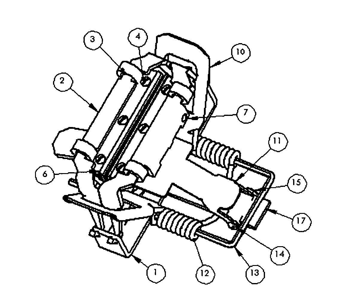
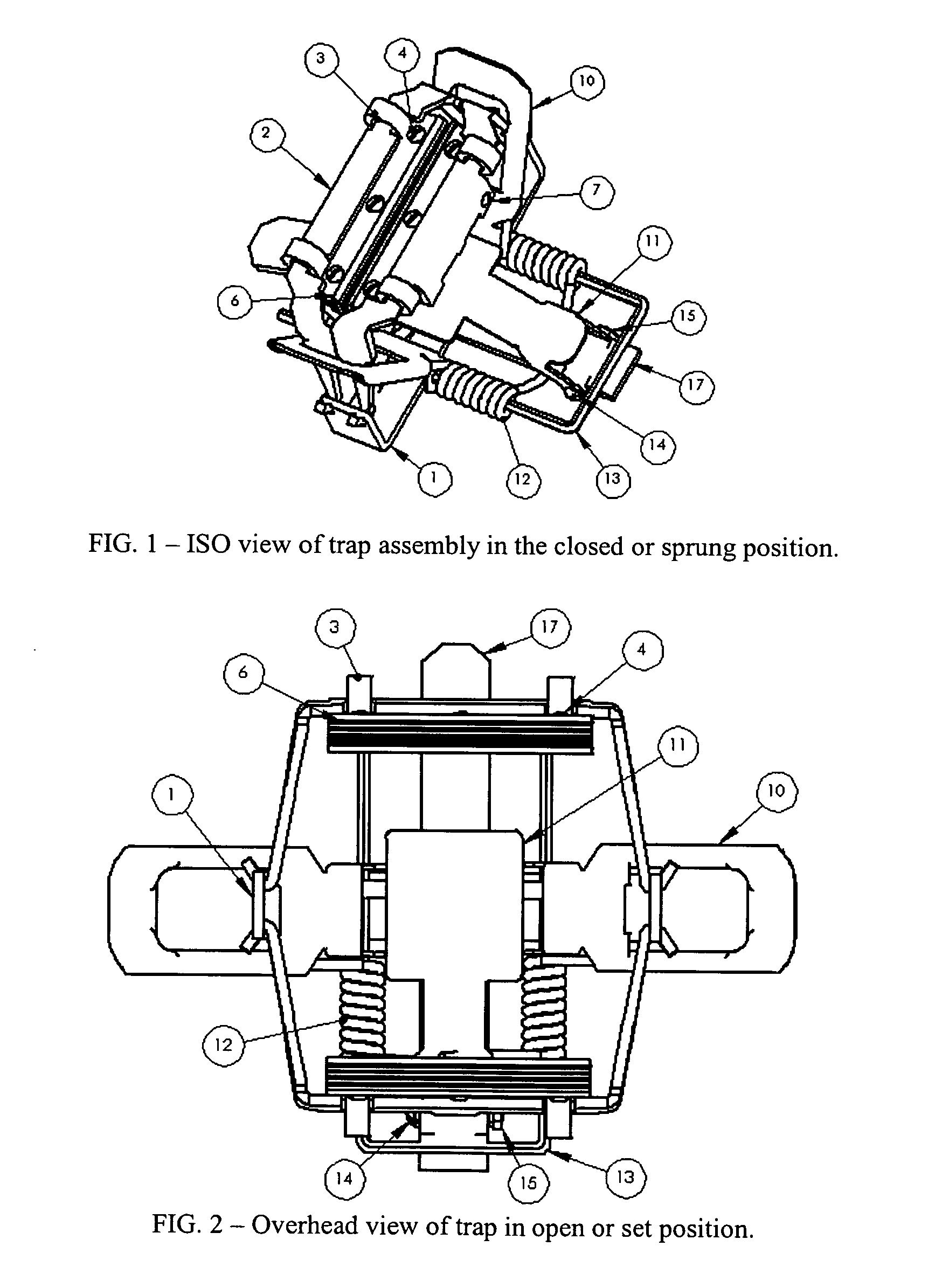
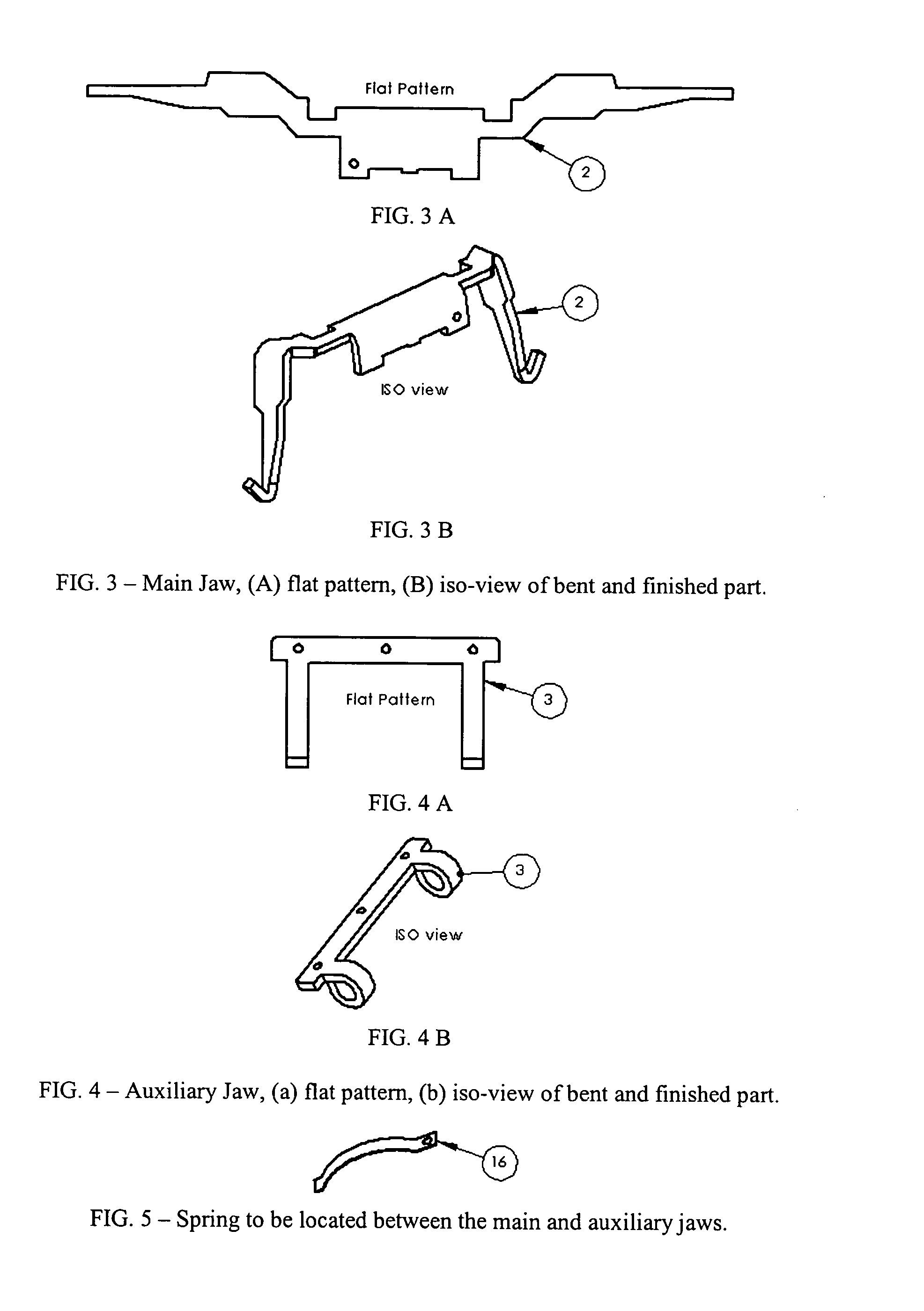
[0021] The substantially U-shaped main jaws are shown in detail in their preferred embodiment in FIG. 3. Two of these main jaws must be created for every trap assembly. The flat pattern is cut or stamped from a sheet of preferably steel, followed by bending processes to finish the part. Notches near the comers of the main jaw on the topmost corners will serve as rotation points for the auxiliary jaw subassembly. This rotat...


PUM


Abstract

Disclosed is an animal trap with a rotating auxiliary jaw subassembly attached to each of two substantially U-shaped trap main jaws. The invention is such that it reduces the impact force with an animal's leg upon closing. Additionally, the invention allows for increased holding power when the animal pulls away from the trap, but allows for reduced clamping force upon animal relaxation with the intent of allowing restored blood flow to the clamped area of the animal's extremity. Preferred embodiments include a padded jaw construction for additional reduction in impact force.

Description

CROSS-REFERENCE TO RELATED APPLICATION [0001] Not Applicable STATEMENT REGARDING FEDERALLY SPONSORED RESEARCH OR DEVELOPMENT [0002] Not Applicable REFERENCE TO SEQUENCE LISTING, A TABLE, OR A COMPUTER PROGRAM LISTING COMPACT DISC APPENDIX [0003] Not Applicable BACKGROUND OF THE INVENTION [0004] This invention relates to traps for catching wild animals with reduced chance of injury to the animals, while improving the likelihood of holding the animal. [0005] In the past, there have been many attempts at creating traps with reduced risk of injury to the animal, [U.S. Pat. Nos. 6,751,901; 6,732,471; 4,817,313; 4,711,049; 4,638,590; 2,083,451; 1,913,893; 1,907,360]. Many of these concepts have involved the use of a snare type trap in which damage to the animal is reduced specifically during trap actuation or closing on the animal's leg. None of these traps have proven to be effective in terms of long term operation for capturing and holding the animals. [0006] While traps have taken many...

Claims


Application Information

Patent Timeline
Patent Type & Authority Applications(United States)
IPC IPC(8): A01M23/26
CPCA01M23/26
Inventor PEDERSEN, LARRY EDWARDPEDERSEN, WILLIAM EDWARD
Owner PEDERSEN LARRY EDWARD
Why Eureka
Try Eureka