
Circular building structure and method of constructing the same

a technology of building structure and circular structure, which is applied in the direction of building roofs, climate sustainability, human health protection, etc., can solve the problems of vertically disposed vertical fins or brackets, the force opposing the force produced by the structure tension, and achieve the effect of sufficient strength

Inactive Publication Date: 2007-10-25
OWENS CLARENCE
View PDF8 Cites 11 Cited by
  • Summary
  • Abstract
  • Description
  • Claims
  • Application Information

AI Technical Summary

Benefits of technology

[0009]It is an object of the present invention to provide an improved circular building structure of sufficient strength to be able to withstand hurricane force winds and which overcomes the disadvantages of the prior art discussed above.
[0011]According to the present invention any forces that may extend along the length of each beam toward the beam tube are opposed by the beam tube since the shape thereof causes it to resist compression forces. As per the present invention, the beam tube can more effectively oppose compression forces from the beams since the shape of the beam tube causes such forces to be distributed across the surface of the beam tube, thereby not concentrating such forces on the flange or on the fastener which attaches the end of the beam to the flange.
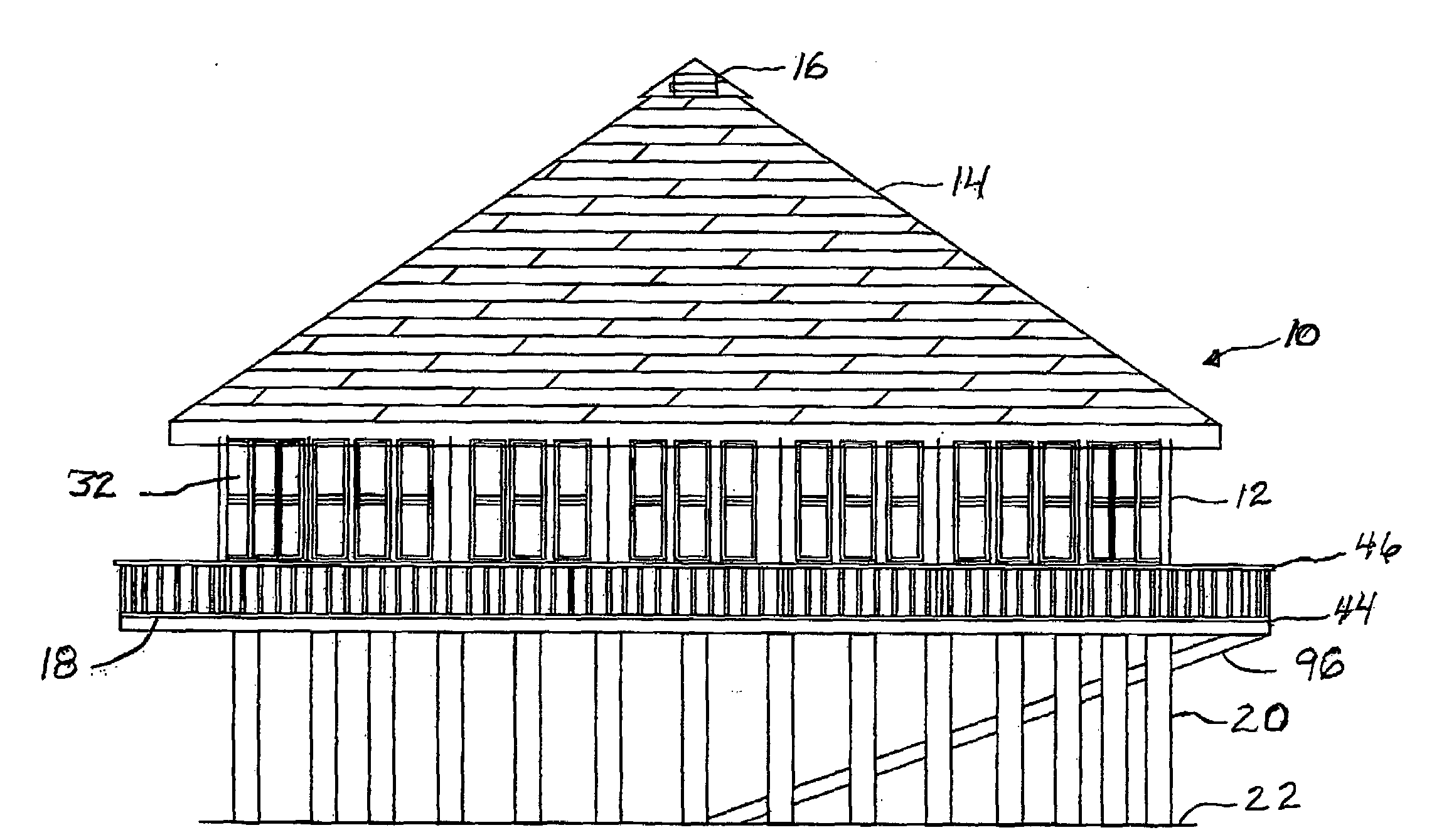
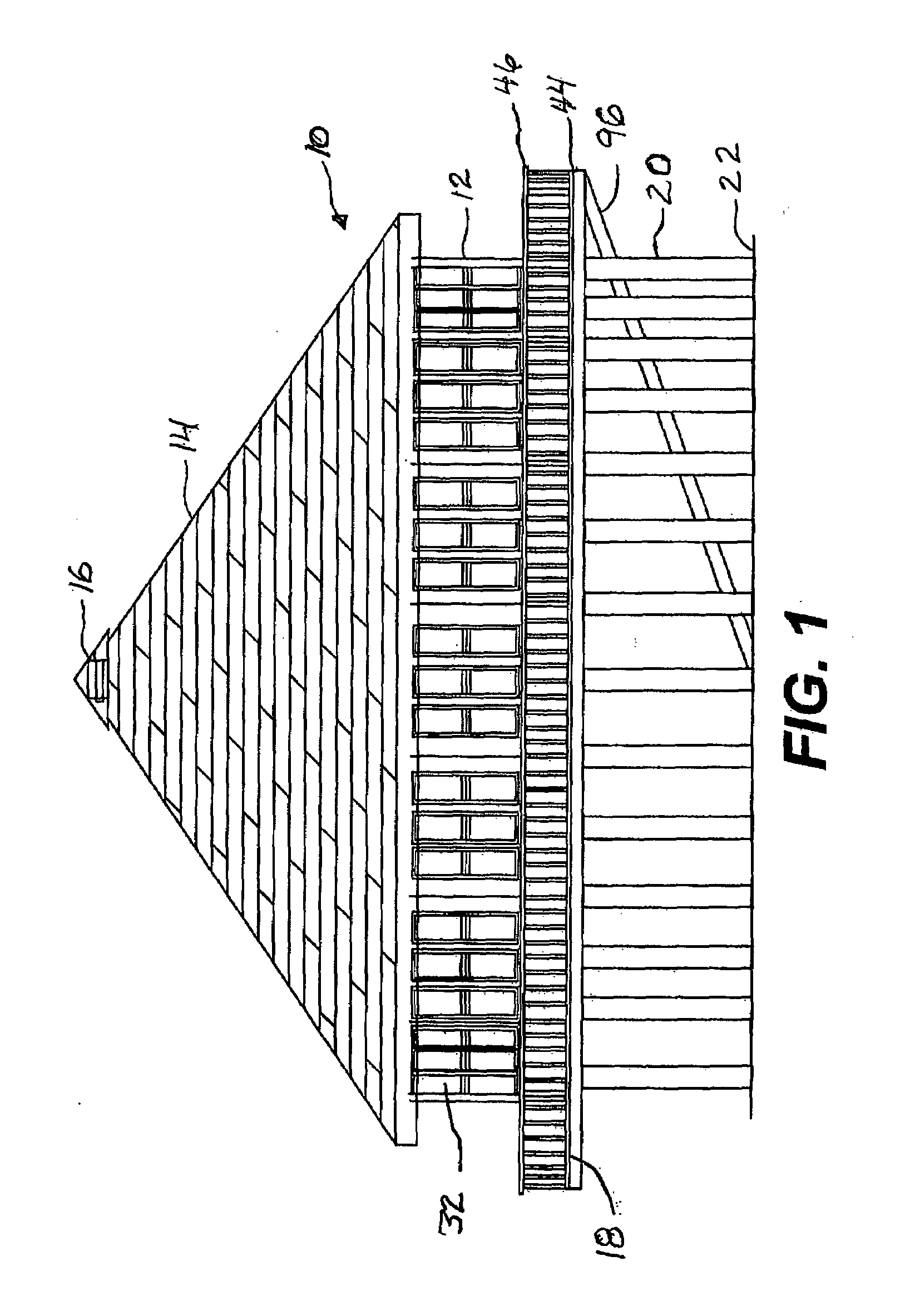
[0012]The present invention also includes various other features that add to the rigidity thereof. Further, these various features also allow the structure to withstand high, hurricane force, winds, efficiently channel water away from the structure to minimize water damage and maintain the interior of the structure dry and cause the structure to be energy efficient. These features include (1) setting the posts which form a part of the wall structure at predetermined distances from each other, (2) using tongue and groove construction to fit the floor boards of the floor to each other, (3) fixing the circular band to the top edge of the wall structure so as to prevent expansion of the wall structure due to the load of the roof, with the band being attached to each of the posts of the wall structure, (4) constructing the floor so that it tapers towards the center of the cylindrical structure to aid in water drainage, (5) providing louvers or air vents at preset locations in the floor, particularly near the center and near the periphery of the floor to aid in air circulation and ventilation, (6) constructing the windows so that they have a curved shape so as to reduce energy transmission and 7) extending the floor outwardly beyond the walls to form a circular walkway all around the structure.

Problems solved by technology

A disadvantage of the central ring 76 as taught by Leslie is that the only force opposing the force produced by the tension in the structure is the vertically disposed vertical fins or brackets.

Method used


Image

  • Circular building structure and method of constructing the same
  • Circular building structure and method of constructing the same
  • Circular building structure and method of constructing the same

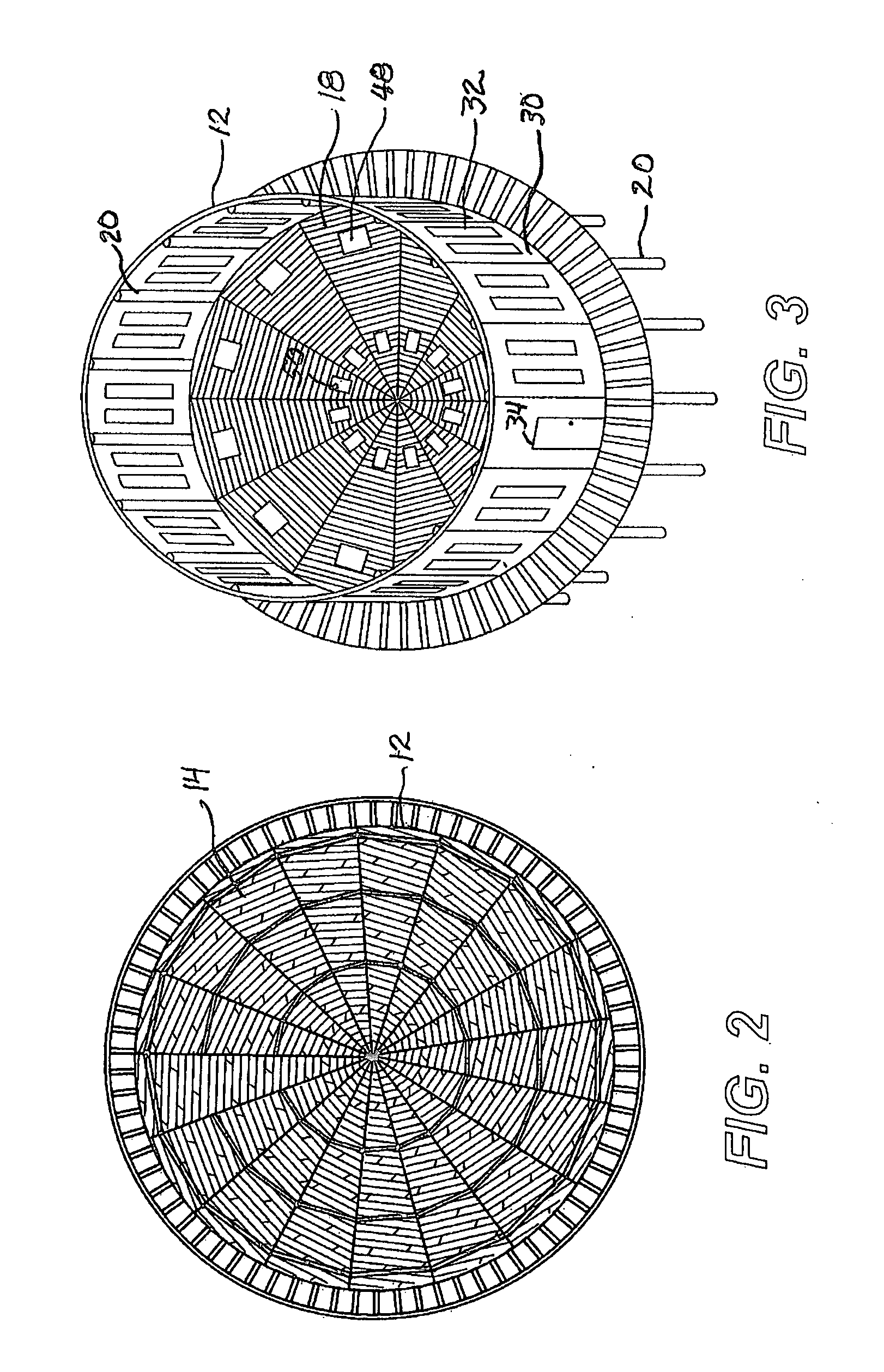
Examples


Embodiment Construction

[0027]Applicant's invention provides an improved circular building structure suitable for a residence and other buildings and which possesses substantial strength capable of withstanding hurricane force winds. In a preferred embodiment, the circular building structure is supported above the level of a surface by a plurality of spaced posts embedded in the surface.

[0028]Shown in the drawings is a circular building structure 10 having a conically shaped roof 14 provided with a cylindrical beam tube 16 at the top thereof and having a generally cylindrical side wall 12 extending upwardly from a floor 18. Preferably the structure 10 is supported at an elevated level above a supporting surface such as ground 22 by a plurality of spaced posts 20 extending around the perimeter of the building. The posts 20 preferably are a total of 24 feet in length and are buried four feet in the ground, extend eight feet above ground to the floor level and continue for another 12 feet to form wall support...


PUM


Abstract

A circular building structure includes a floor, a cylindrical wall extending upwardly from the floor, and a roof mounted on top of the cylindrical side wall. The roof is constructed of a plurality of roof beams which are supported by and extend radially and upwardly from a perimeter of the cylindrical wall toward the center to form a peak having a cylindrical beam tube disposed therein. A plurality of flanges are attached to an outer wall of the beam tube to support the upper inner end of each roof beam and brackets are mounted to the top of the side wall to support the lower ends of the roof beams. A circular band extends around the perimeter of and is attached to the upper end of the circular wall. The structure may be elevated above ground level and a walkway constructed all around the perimeter thereof at a floor level.

Description

BACKGROUND OF THE INVENTION[0001]1. Field of the Invention[0002]The present invention relates generally to building structures. More particularly, the present invention relates to a circular building structure of sufficient strength so as to be capable of withstanding hurricane force winds and which may be used in residential housing and a method of constructing the structure.[0003]2. Description of the Related Art[0004]Circular dwellings are well known as evidenced by U.S. Pat. No. 6,722,091 (Leslie) and U.S. Pat. No. 2,256,050 (Hansen).[0005]Leslie discloses a circular house which includes at least one wall panel placed under tension by bending the wall panel from a flat form to a curved form. The tension is intended to provide rigidity and strength to the wall panel. A preferred form of the house includes two tensioned wall panels with the concave faces of the wall panels confronting each other such that a generally circular residential house is formed. A counter to oppose the te...

Claims


Application Information

Patent Timeline
IPC IPC(8): E04B7/00
CPCE04B1/26E04B1/2604E04H9/14E04B2001/0061E04B7/028Y02A50/00
Inventor OWENS, CLARENCE
Owner OWENS CLARENCE
Learn More