
Transport container, transporting method for the same, and constant temperature transport container

a technology of transport container and transporting method, which is applied in the direction of transportation and packaging, domestic cooling apparatus, lighting and heating apparatus, etc., to achieve the effect of prolonging the temperature retaining time and small heat radiation area

Inactive Publication Date: 2007-10-25
HITACHI LTD
View PDF7 Cites 22 Cited by
  • Summary
  • Abstract
  • Description
  • Claims
  • Application Information

AI Technical Summary

Benefits of technology

[0015]The transport container described in the Patent Document 1 can hold a transported object within a predetermined temperature range by a simple constitution. Further, the transport container described in the Patent Document 2 transfers cool and hot heat generated by the Peltier element to the metallic container and via the air flow circulating inside of the container, controls the temperature of the transported object with high precision. However, the transport containers described in the Patent Documents 1 and 2 leave room for reducing the heat radiation amount.
[0018]An object of the present invention, in a constant temperature transport container with a simple constitution, is to keep the temperature of a transported object within a predetermined temperature range for a long time. Another object of the present invention is to enable transport of a transported object such as cells etc. at a constant temperature over a long period of time. And, it is an object to accomplish at least one of the objects.
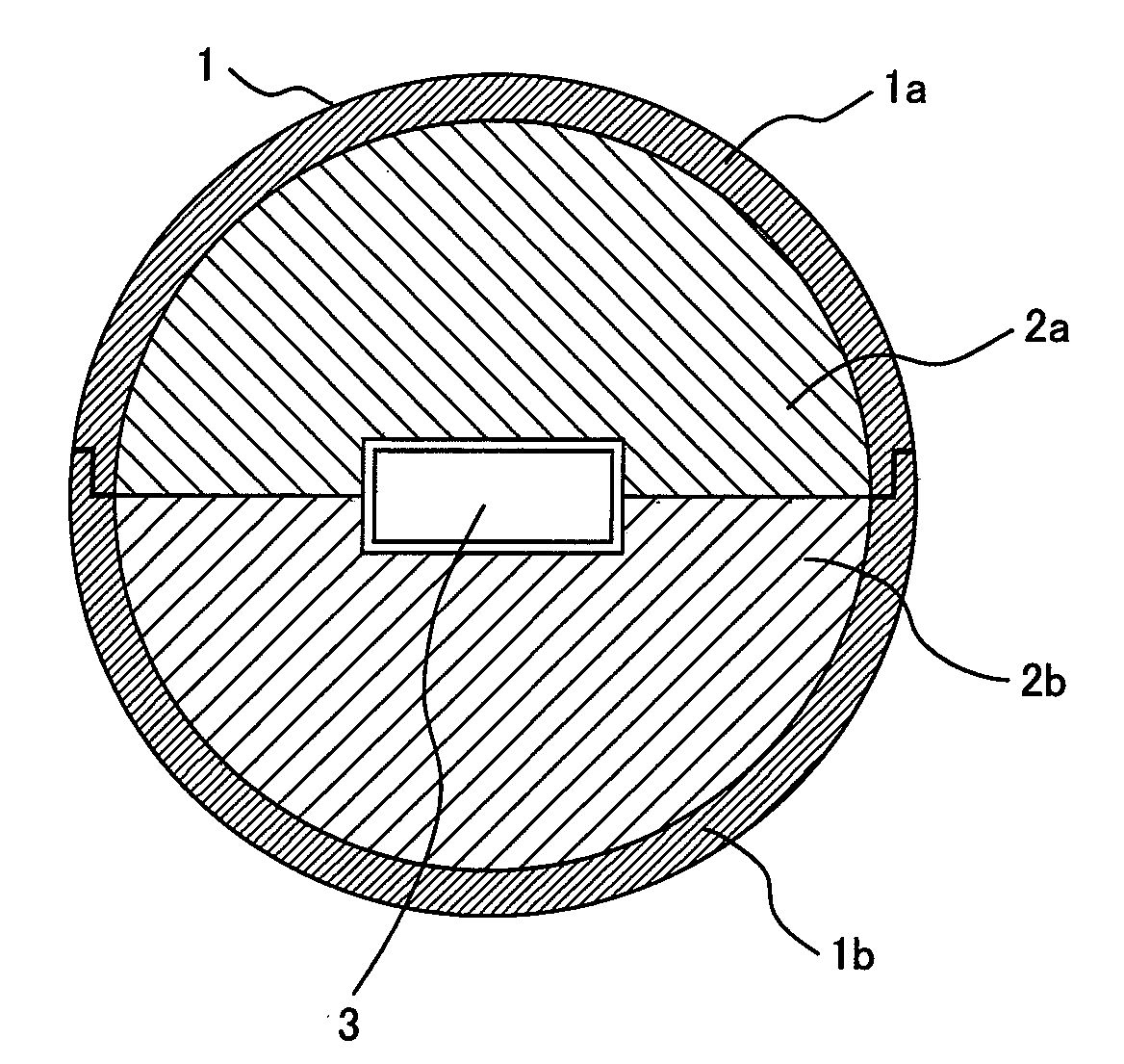
[0020]According to the present invention, the heat accumulating material is arranged in a spherical shape around the transported object, so that almost all of the quantity of heat possessed by the heat accumulating material can be used to retain the temperature of the transported object. Further, the transport container is spherical, so that the heat radiation area is small and the temperature retaining time can be prolonged.

Problems solved by technology

However, the transport containers described in the Patent Documents 1 and 2 leave room for reducing the heat radiation amount.

Method used


Image

  • Transport container, transporting method for the same, and constant temperature transport container
  • Transport container, transporting method for the same, and constant temperature transport container
  • Transport container, transporting method for the same, and constant temperature transport container

Examples


Embodiment Construction

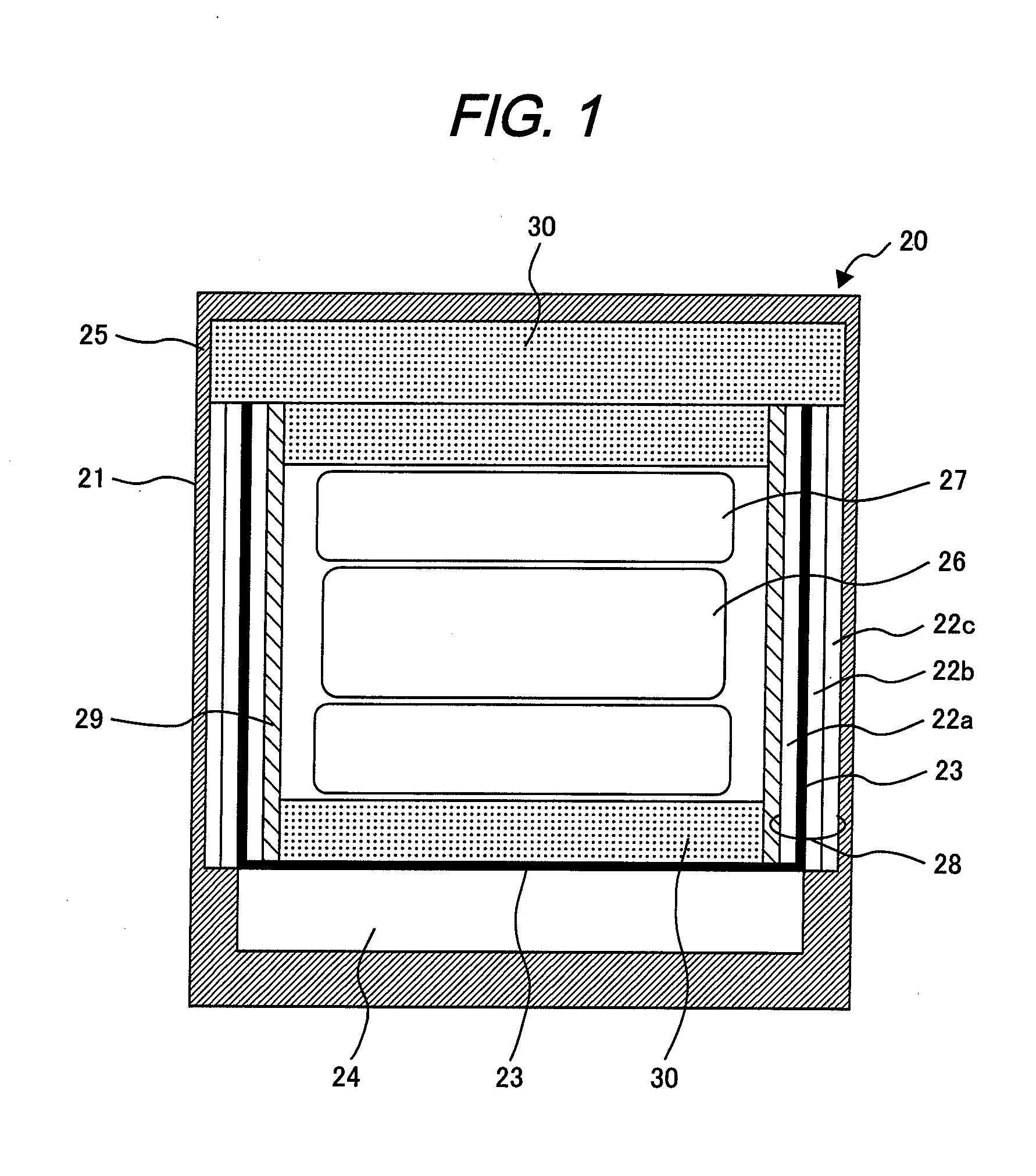
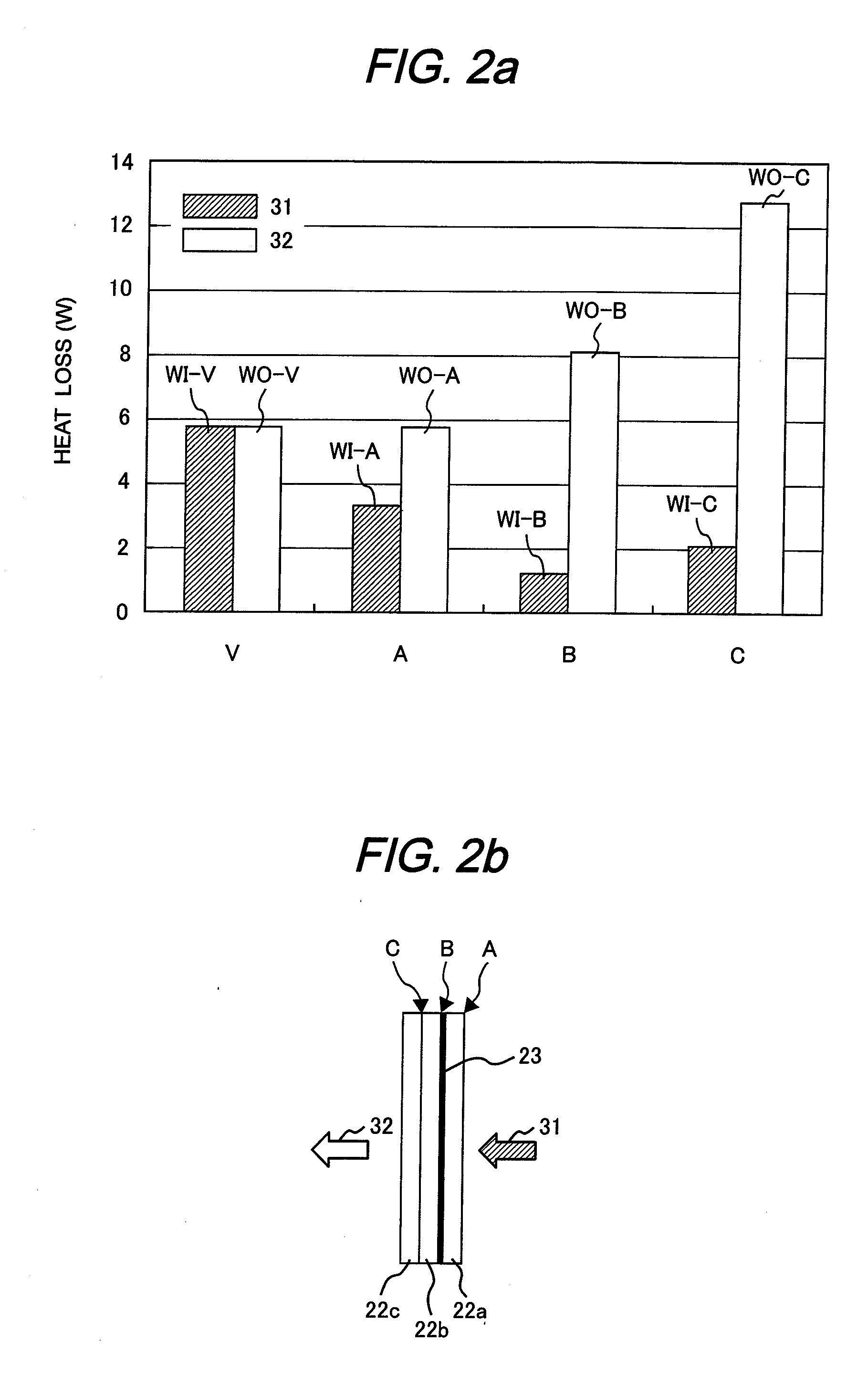
[0028]Hereinafter, an embodiment of the constant temperature transport container relating to the present invention will be explained with reference to FIGS. 1 and 2.

[0029]FIG. 1 shows a longitudinal cross sectional view of the constant temperature transport container. A constant temperature transport container 20 is composed of a heat insulating container 21, a heat insulating wall 28 combining a plurality of heat insulators such as vacuum heat insulators 22a, 22b, and 22c and a heat conductive member 23 such as heat conductive copper or aluminum, a cushioning material 30 using a material of expanded polystyrene, urethane foam, or sponge, and a protective material 29.

[0030]Inside of the constant temperature transport container 20, a heat accumulating container 27 for storing a first heat accumulating material and a heat accumulating container 26 for storing a transported object and the first heat accumulating material are installed. Here, the vacuum heat insulator is formed by seali...


PUM


Abstract

A transport container comprising a spherical container 1 and a heat accumulating material 2a, 2b disposed inside of the spherical container 1, wherein; the heat accumulating material 2a, 2b is provided with a space for holding a transported object therein, and the space is formed at the central part of the inside of the spherical container 1.

Description

CLAIM OF PRIORITY[0001]The present application claims priority from Japanese application serial No. 2006-116284, filed on Apr. 20, 2006, the contents of which is hereby incorporated by reference into this application.BACKGROUND OF THE INVENTION[0002]1. Field of the Invention[0003]The present invention relates to a container for storing biocells or cellular tissue medical instruments and a transport container for transporting them.[0004]2. Prior Art[0005]Cultured cells used for regenerating medical treatment is desirably transported from a culture installation to a hospital under the same condition as the culture temperature. For that purpose, a strict temperature control technology is necessary. To keep temperature inside of a transport container uniform, a temperature control apparatus comprising a cool-heat generator, a hot temperature generator, a circulating means for fluid in side of the container, and a control means and a heat insulating means for insulating a heat transfer b...

Claims


Application Information

Patent Timeline
Patent Type & Authority Applications(United States)
IPC IPC(8): F25D3/08
CPCF25D2303/0845F25D3/08F25D2303/0844F25D2303/0843F25D2303/0831
Inventor UCHIDA, MARIKUSUMOTO, HIROSHIMATSUSHIMA, HIROAKI
Owner HITACHI LTD
Learn More