Gasification technology burner protection device and protection method

A technology of process burner and gasifier, which is applied in the direction of gasification process, details of gasification device, chemical instruments and methods, etc., can solve the problem of reduced free volume of process burner chamber, easy damage of process burner, and reduced service life. And other issues

Pending Publication Date: 2017-12-12
HENAN XINLIANXIN FERTILIZER
View PDF6 Cites 2 Cited by
  • Summary
  • Abstract
  • Description
  • Claims
  • Application Information

AI Technical Summary

Problems solved by technology

[0002] The coal gasification process burner is one of the very important production devices in coal chemical enterprises. In the actual production process, the service life of the process burner will be shortened due to various reasons that are unfavorable to the process burner. Generally, the gasification process burner The replacement cycle is 2 months
This not only delays the production time due to the replacement of the process burner in the production process, but also affects the production economy of the enterprise to some extent
At present, the problem of short service life of process burners in China is still a difficult problem in the industry. Most of them have the following problems: a. The front end of the oxygen nozzle outside the process burner faces the high-temperature process gas and secondary combustion particles in the gasifier. Under certain conditions, the alternation of oxidizing and reducing gases, as well as the wear of solids, th

Method used


Image

  • Gasification technology burner protection device and protection method
  • Gasification technology burner protection device and protection method
  • Gasification technology burner protection device and protection method

Examples


Embodiment 1

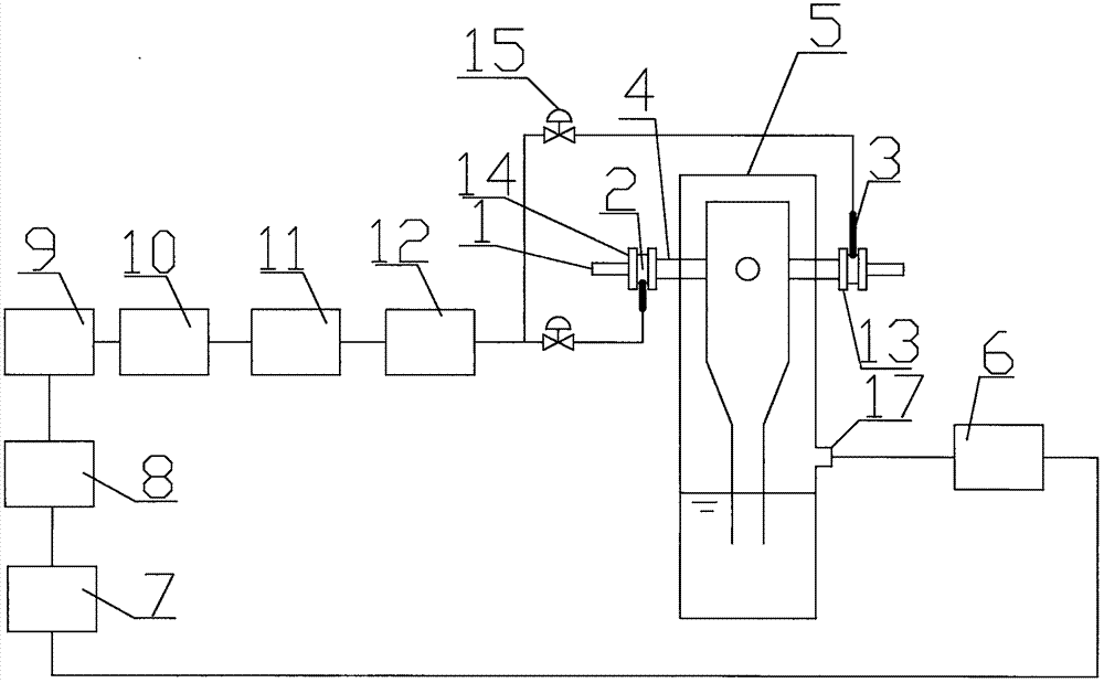
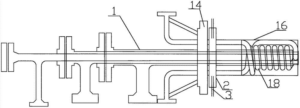
[0036] A protective gasification process burner device and protection method, wherein the protective gasification process burner device includes a gasification furnace 5, and several process burner chambers 4 are arranged on the upper part of the gasification furnace 5, and the process burner chamber 4 The gasification process burner is connected, and the bottom of the gasification furnace 5 is provided with a crude synthesis gas outlet 17, and the crude synthesis gas outlet 17 passes through the shift furnace 6 and CO 2 7 connected absorption towers, CO 2 The absorption tower 7 sequentially passes the CO 2 Analysis tower 8, CO 2 Compressor 9, first filter 10, second filter 11, heat exchanger 12 and regulating valve 15 and CO 2 The gasification process burner includes a process burner body 1 with coal slurry and oxygen channels. The front end of the process burner body 1 is provided with a cooling circulating water coil 18, and the cooling circulating water coil 18 The wate...

Embodiment 2

[0046] A protective gasification process burner device and protection method, wherein the protective gasification process burner device includes a gasification furnace 5, and several process burner chambers 4 are arranged on the upper part of the gasification furnace 5, and the process burner chamber 4 The gasification process burner is connected, and the bottom of the gasification furnace 5 is provided with a crude synthesis gas outlet 17, and the crude synthesis gas outlet 17 passes through the shift furnace 6 and CO 2 7 connected absorption towers, CO 2 The absorption tower 7 sequentially passes the CO 2 Analysis tower 8, CO 2 Compressor 9, first filter 10, second filter 11, heat exchanger 12 and regulating valve 15 and CO 2 The gasification process burner includes a process burner body 1 with coal slurry and oxygen channels. The front end of the process burner body 1 is provided with a cooling circulating water coil 18, and the cooling circulating water coil 18 The wate...

Embodiment 3

[0056] A protective gasification process burner device and protection method, wherein the protective gasification process burner device includes a gasification furnace 5, and several process burner chambers 4 are arranged on the upper part of the gasification furnace 5, and the process burner chamber 4 The gasification process burner is connected, and the bottom of the gasification furnace 5 is provided with a crude synthesis gas outlet 17, and the crude synthesis gas outlet 17 passes through the shift furnace 6 and CO 2 7 connected absorption towers, CO 2 The absorption tower 7 sequentially passes the CO 2 Analysis tower 8, CO 2 Compressor 9, first filter 10, second filter 11, heat exchanger 12 and regulating valve 15 and CO 2 The gasification process burner includes a process burner body 1 with coal slurry and oxygen channels. The front end of the process burner body 1 is provided with a cooling circulating water coil 18, and the cooling circulating water coil 18 The wate...


PUM


Abstract

The invention belongs to a gasification technology burner protection device and a protection method. The gasification technology burner protection device comprises a gasification furnace, wherein a plurality of technology burner chambers are arranged at the upper part of the gasification furnace; each technology burner chamber is internally provided with a gasification technology burner and is connected with the gasification technology burner; a crude synthetic gas outlet is formed in the bottom of the gasification furnace; the crude synthetic gas outlet is connected with a CO2 absorption tower through a conversion furnace; the CO2 absorption tower is connected with a CO2 gas inlet hole through a CO2 resolving tower, a CO2 compressor, a first filter, a second filter, a heat exchanger and a regulating valve in sequence; the gasification technology burner comprises a technology burner body with a coal slurry and oxygen channel; a technology burner flange disc is adaptive to a flange at the end part of each technology burner chamber; the CO2 gas inlet hole is formed in the radial direction of an annular gasket. The gasification technology burner protection device has the advantages that the structure is simple, a technology design is reasonable, a thermal stress self-compensation space of the technology burner and a cooling water coiled pipe is established, relatively great thermal stress of the technology burner and the cooling water coiled pipe is prevented, the abrasion of the technology burner is reduced and the service life is prolonged.

Description

technical field [0001] The invention belongs to the technical field of protective gasification process burner devices, and in particular relates to a protective gasification process burner device and a protection method. Background technique [0002] The coal gasification process burner is one of the very important production devices in coal chemical enterprises. In the actual production process, the service life of the process burner will be shortened due to various reasons that are unfavorable to the process burner. Generally, the gasification process burner The replacement cycle is 2 months. This not only delays the production time due to the replacement of the process burner in the production process, but also affects the production economy of the enterprise to some extent. At present, the problem of short service life of process burners in China is still a difficult problem in the industry. Most of them have the following problems: a. The front end of the oxygen nozzle...

Claims


Application Information

Patent Timeline
IPC IPC(8): C10J3/50C10J3/48C10J3/46C10J3/82C01B3/50C01B32/50
CPCC10J3/46C10J3/48C10J3/50C10J3/82C01B3/50C01B3/52C01B2203/0415C10J2200/152C10J2300/1603C10J2300/093C10J2300/0959
Inventor 孙玉龙郝春源王洪营曹真真张超杨传琦崔玉彪余复幸
Owner HENAN XINLIANXIN FERTILIZER
Why Eureka
Try Eureka