Continuous positive airway pressure device and configuration for employing same

a positive airway and pressure device technology, applied in the field of patient ventilation systems, can solve the problems of poor judgment, severe and even life-threatening consequences, irritability, memory loss, etc., and achieve the effect of convenient and comfortable us

Active Publication Date: 2007-10-25
CAREFUSION
View PDF0 Cites 28 Cited by
  • Summary
  • Abstract
  • Description
  • Claims
  • Application Information

AI Technical Summary

Benefits of technology

[0019] The liner may include an opening through which the halves or sections may be inserted. Ideally, the portable housing assembly are sized and configured such that the resilient material provides sufficient padding such that the patient may use any of the above-mentioned configurations as a pillow or for support

Problems solved by technology

Left untreated, OSA can lead to severe and even life-threatening consequences.
Serious cases of OSA can result in sleep deprivation or insomnia which, over time, can result in moodiness, irritability, memory loss, poor judgment and an overall poor quality of life.
Even further, patients suffering from OSA have a dramatically increased risk of traffic accidents and an increased mortality rate due to medical complications stemming from this disorder.
The torqueing or pulling by the patient hose results in poor sealing of the mask against the patient's face.
In addition, the sideways pulling on the mask may also create pressure points against the patient's face and results in general patient discomfort.
For patients who use nasal prongs, the sideways tugging can cause irritation of the patient's nose due to the close-fitting engagement of the prongs with tender mucous tissue lining the patient's nostrils.
For patients who use a nasal mask which seals around an exterior of the patient's nose, the tugging of the patient hose can prevent proper sealing of the mask and can also cause eye irritation as a result of pressurized gas leak

Method used


Image

  • Continuous positive airway pressure device and configuration for employing same
  • Continuous positive airway pressure device and configuration for employing same
  • Continuous positive airway pressure device and configuration for employing same

Examples


Embodiment Construction

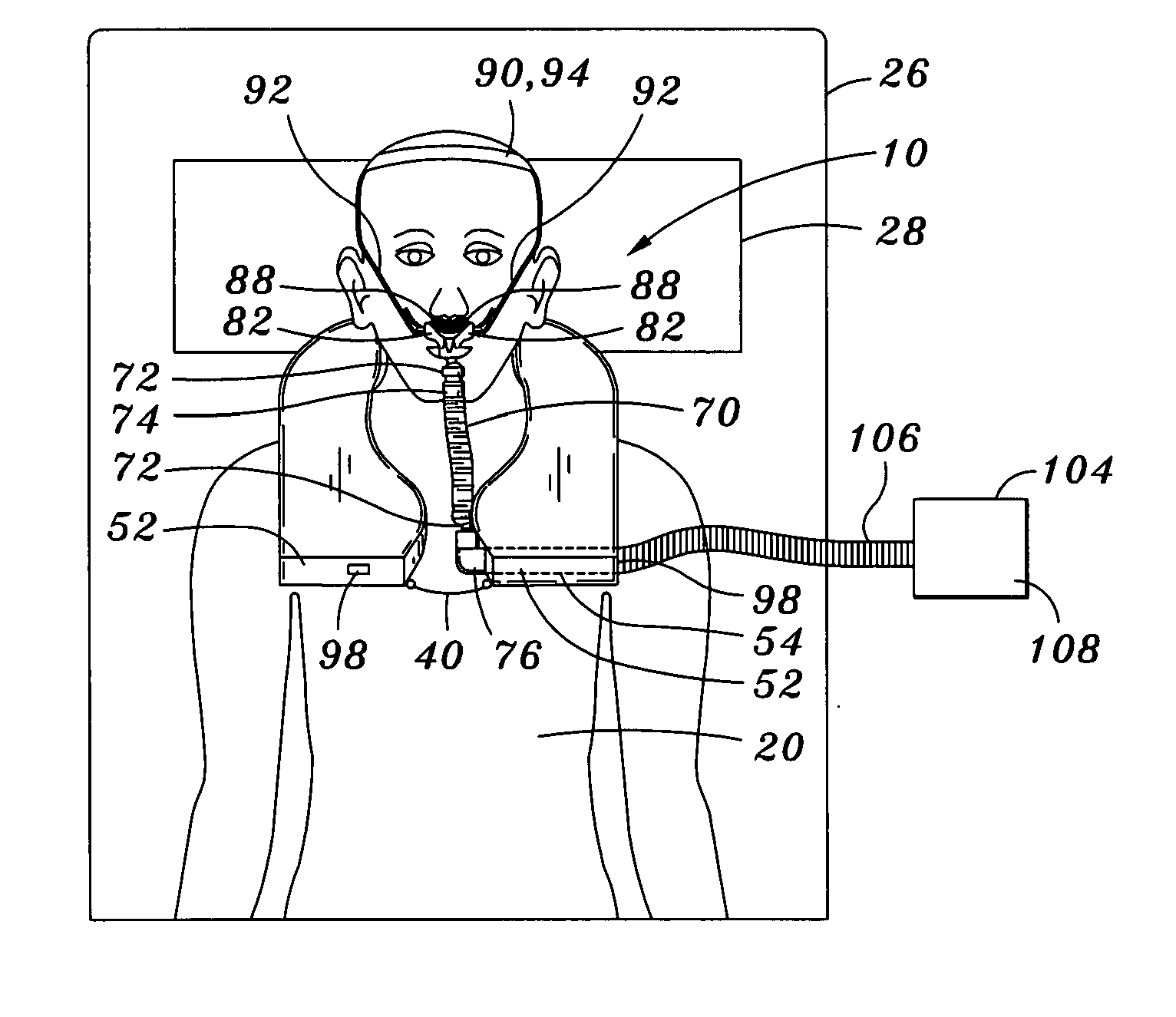
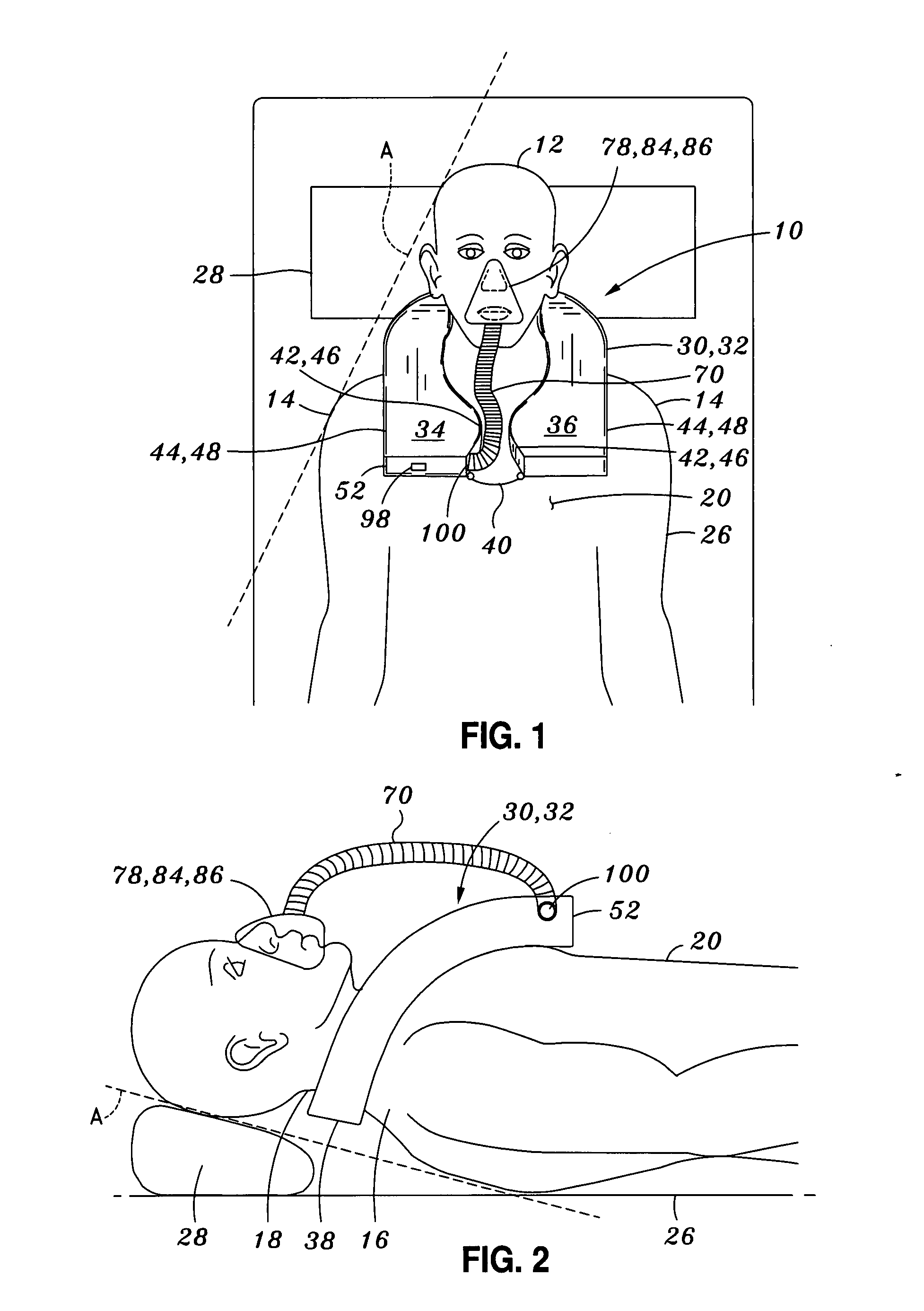
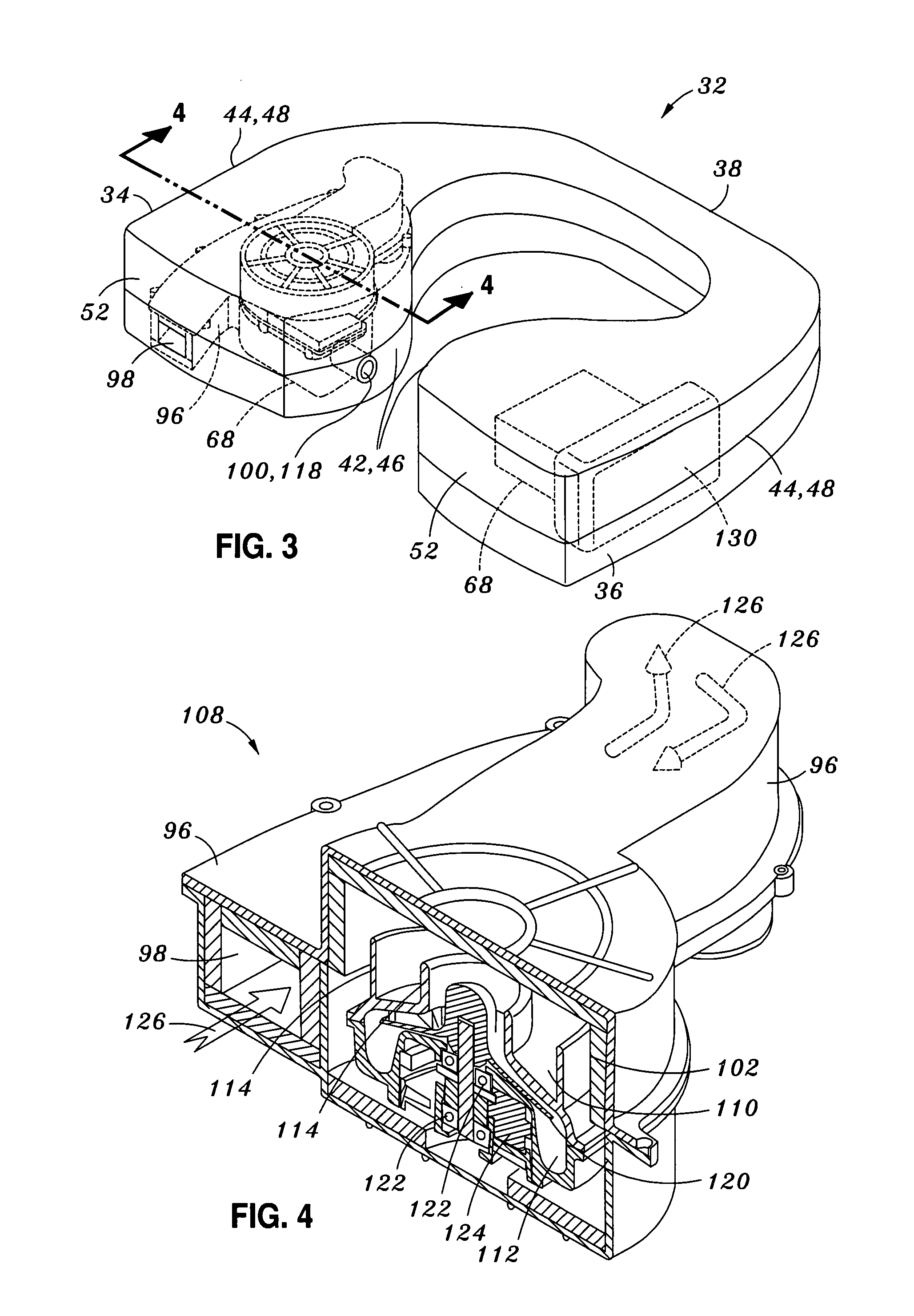
[0033] Referring now to the drawings wherein the showings are for purposes of illustrating preferred embodiments of the present invention and not for purposes of limiting the same, shown is a portable continuous positive airway pressure (CPAP) device 10 adapted for delivering gas under pressure to a patient 12. In its broadest sense, the CPAP device 10 comprises a portable housing assembly 30, a motor blower unit 108, a user interface 78, and a patient hose 70 extending between the user interface 78 and the motor blower unit 108. In one embodiment, the portable housing assembly 30 is specifically adapted to be worn by or attached to the patient 12 in order to avoid the problem of prior art CPAP devices in which the patient hose 70 tugs against the patient mask.

[0034] More particularly, such prior art CPAP devices typically include a bedside blower unit connected by a lengthy patient hose to a nasal mask 86 or nasal prongs 88 (i.e., user interface 78) mounted on the patient's face. ...


PUM


Abstract

A portable continuous positive airway pressure (CPAP) device is adapted for delivering gas under pressure to a patient. The CPAP device comprises a portable housing assembly, a motor blower unit disposable within the portable housing assembly, a user interface configured to be engaged to the patient, and a patient hose extending between the user interface and the motor blower unit. The portable housing assembly may be comprised or configured as a wearable frontpack assembly which is configured to be worn against the patient's chest. The frontpack assembly may include a pair of shoulder straps configured to extend over the patient's shoulders and under the patient's arms to secure the CPAP device to the patient. The motor blower unit may be remotely disposed from the portable housing assembly such as on a bedside assembly or on a tabletop stand.

Description

CROSS-REFERENCE TO RELATED APPLICATIONS [0001] The present application claims priority to U.S. Provisional Application Nos. 60 / 793,433 and 60 / 793,589 and 60 / 793,704, each filed on Apr. 20, 2006, the entire contents of each being expressly incorporated by reference herein. The present application is also related to commonly-owned U.S. Utility Pat. No. 7,195,014 entitled PORTABLE CONTINUOUS POSITIVE AIRWAY PRESSURE SYSTEM filed on May 13, 2005, and to U.S. Utility patent application Ser. No. 11 / 649,674 entitled USER INTERFACE AND HEAD GEAR FOR A CONTINUOUS POSITIVE AIRWAY PRESSURE DEVICE filed on Jan. 4, 2007, the entire contents of each being incorporated by reference herein. STATEMENT RE: FEDERALLY SPONSORED RESEARCH / DEVELOPMENT [0002] (Not Applicable)BACKGROUND [0003] The present invention relates generally to patient ventilation systems and, more particularly, to a uniquely-configured portable continuous positive airway pressure (CPAP) device that may be worn by a patient and whic...

Claims


Application Information

Patent Timeline
IPC IPC(8): A61M15/00A61M16/00A61M15/08
CPCA61M16/0057A61M16/0066A61M16/0683A61M2209/082A61M2205/42A61M2205/8206A61M2205/8237A61M16/08A61M2205/0266A61M16/0825
Inventor HOFFMAN, LESLIE
Owner CAREFUSION
Why Eureka
Try Eureka