Method Of Making A Structural Element For Aeronautical Construction Comprising Differential Work-Hardening
- Summary
- Abstract
- Description
- Claims
- Application Information
AI Technical Summary
Problems solved by technology
Method used
Image
Examples
example 1
[0078]A 25 mm thick plate with variable properties within the plate is made of an AA2023 alloy.
[0079]A 30 meter long, 2.5 meter wide and 28.2 mm thick plate is made by hot rolling of a rolling ingot.
[0080]The composition of the alloy used is given in Table 1 below.
TABLE 1Composition of the rolling ingot made ofAA2023 alloy (% by mass)SiFeCuMgTiZrSc0.060.073.811.360.0240.110.03
[0081]The rolling ingot is homogenized at 500° C. for 12 hours. The hot rolling entry temperature is 460° C.
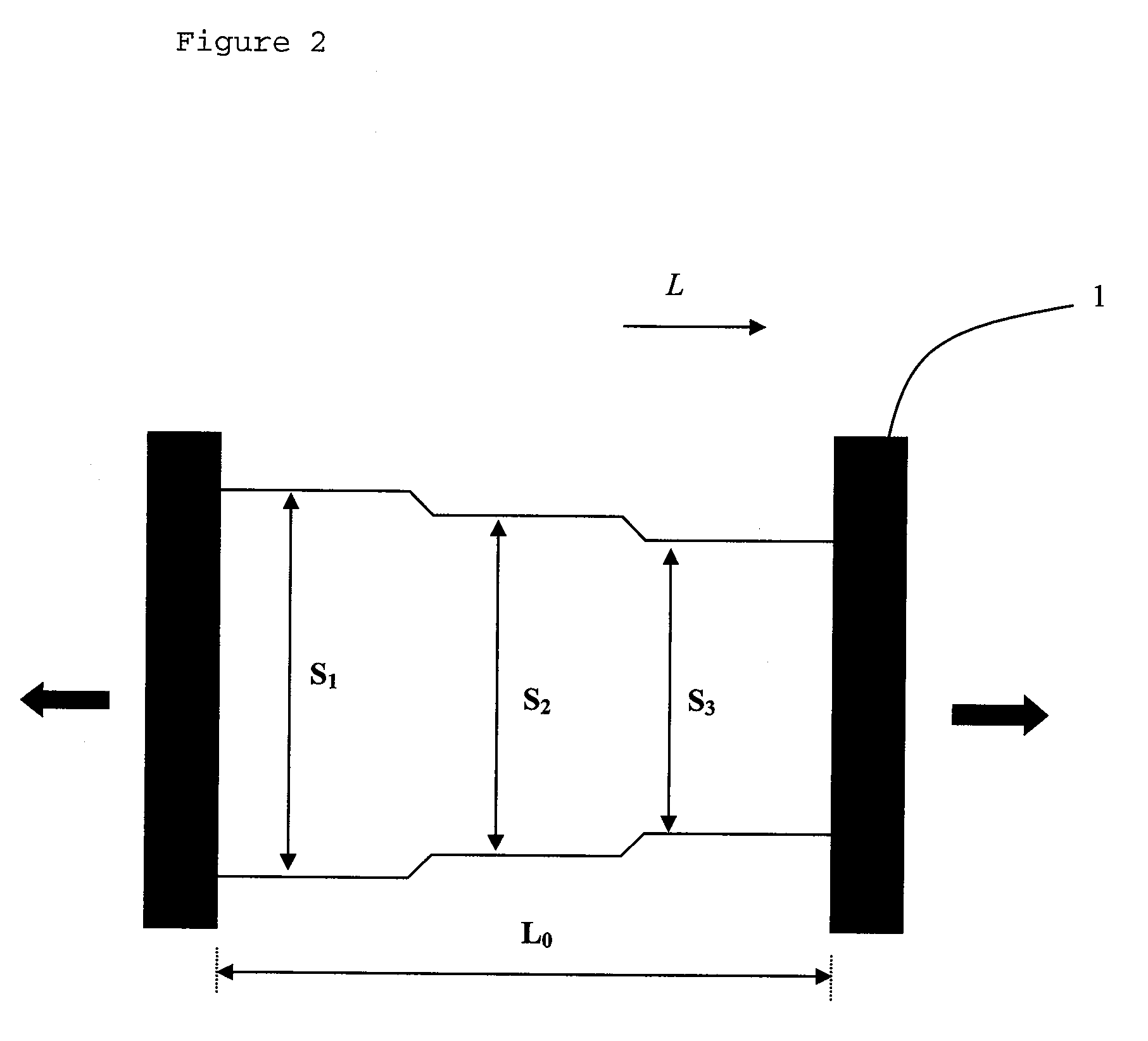
[0082]After hot rolling, the plate is machined as shown on FIG. 3 to obtain three zones Z31, Z32, Z33, with a length equal to 10 meters with the following thicknesses:
[0083]zone Z31: 28.1 m
[0084]zone Z32: 26.3 m
[0085]zone Z33: 25.5 m
[0086]The plate is then solution heat treated at 500° C. and quenched.
[0087]The plate is first cold rolled to obtain a substantially constant thickness of 25.5 mm over the entire plate, and then subjected to controlled stretching with a permanent elongation of about 2%, after ...
example 2
[0092]A 15 mm thick plate with variable properties is made of an AA2024A alloy.
[0093]A 30 meter long, 2.5 meter wide and 16.8 mm thick plate is made by hot rolling of a rolling ingot.
[0094]The composition of the alloy used is given in Table 4 below.
TABLE 4Composition of the rolling ingot made ofAA2024A alloy (% by mass)SiFeCuMnMgTi0.040.073.960.381.290.013
[0095]The rolling ingot is homogenized and then hot rolled.
[0096]After hot rolling, the plate is machined as described in FIG. 3 to obtain three zones Z31, Z32 and Z33 with a length equal to 10 meters with the following thicknesses:
[0097]Zone Z31: 16.7 mm
[0098]Zone Z32: 15.9 mm
[0099]Zone Z33: 15.3 mm
[0100]The plate is then solution heat treated at 500° C. and quenched.
[0101]The plate is first cold rolled to obtain a substantially constant thickness of 15.3 mm over the entire plate, and then subjected to controlled stretching with a permanent elongation of about 2% after which the ends of the piece which were under the jaws of the t...
example 3
[0106]A section with variable properties with a 170×45 mm cross-section is made of a AA2027 alloy.
[0107]A 15 meter long section is made with a 170×45 mm cross-section, by hot extrusion of an extrusion billet.
[0108]The composition of the alloy is given in Table 7 below:
TABLE 7Composition of the rolling ingot made ofAA2027 alloy (% by mass)SiFeCuMnMgZnTiZr0.050.114.20.61.30.060.020.11
[0109]The extrusion billet is homogenized at 490° C. and hot extruded.
[0110]After extrusion, the section is solution heat treated at 500° C. and quenched.
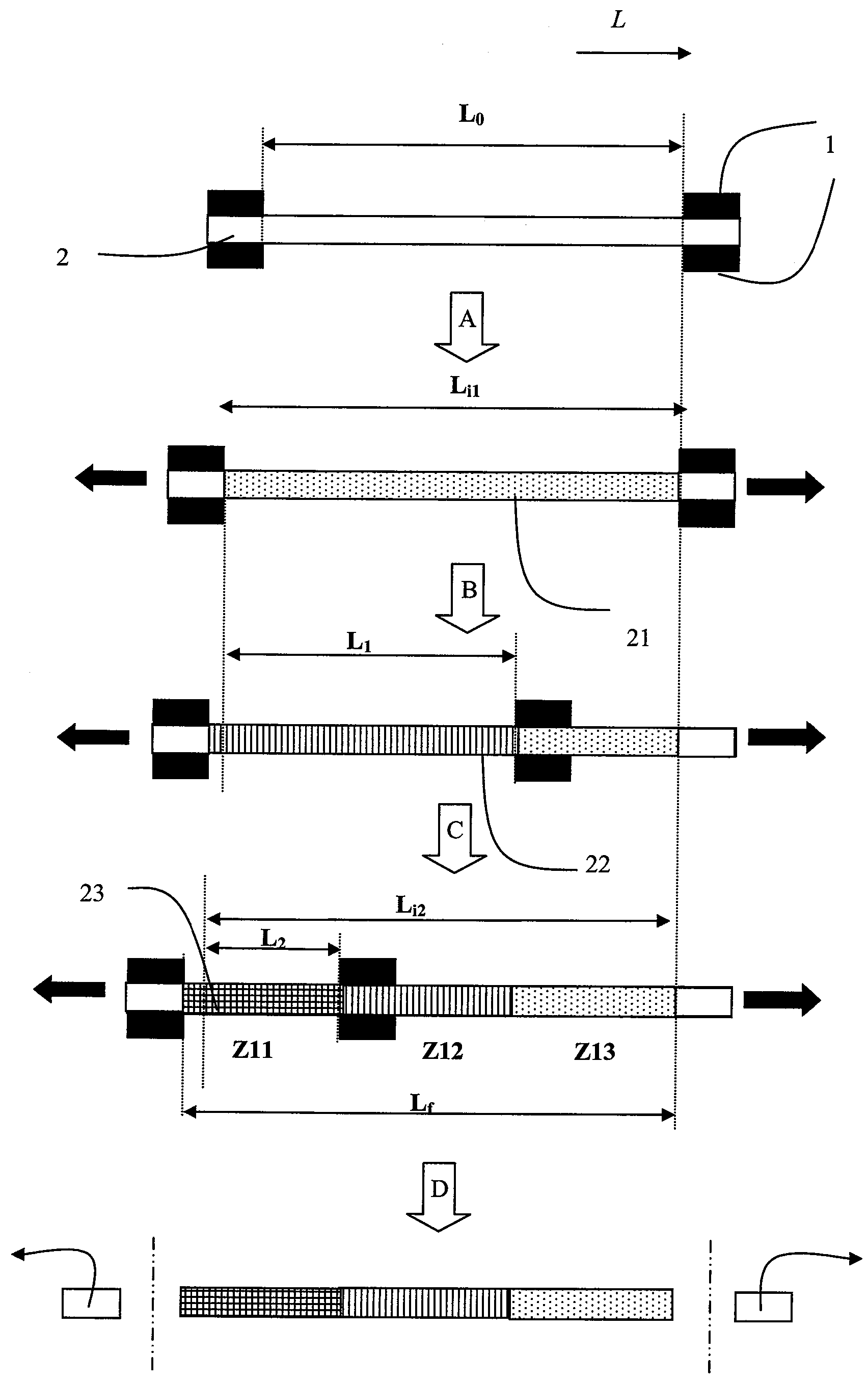
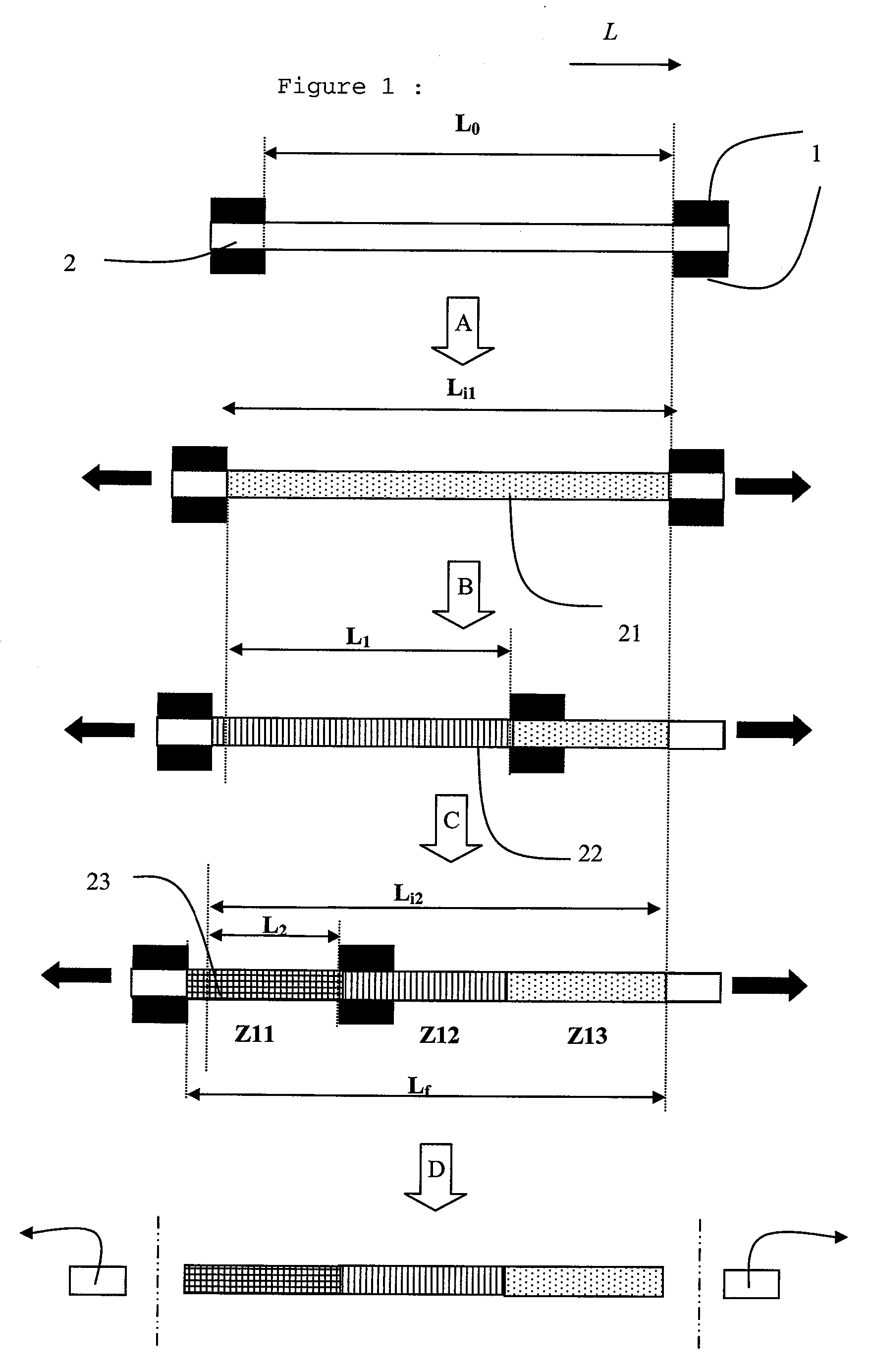
[0111]A first controlled stretching step is then carried out on it with the permanent elongation of 2.8%. One of the jaws of the tension bench is then displaced as shown on FIG. 1, so that one of the ends of the section projects beyond the jaws. A second stretching step is then carried out on the two-thirds of the section (zones Z11 and Z12) located between the jaws with a permanent elongation of 5.6%. The jaw displaced in the second step is then displac...
PUM
| Property | Measurement | Unit |
|---|---|---|
| Fraction | aaaaa | aaaaa |
| Fraction | aaaaa | aaaaa |
| Fraction | aaaaa | aaaaa |
Abstract
Description
Claims
Application Information
 - R&D
- Intellectual Property
- Life Sciences
- Materials
- Tech Scout
- Unparalleled Data Quality
- Higher Quality Content
- 60% Fewer Hallucinations
Browse by: Latest US Patents, China's latest patents, Technical Efficacy Thesaurus, Application Domain, Technology Topic, Popular Technical Reports.
© 2025 PatSnap. All rights reserved.Legal|Privacy policy|Modern Slavery Act Transparency Statement|Sitemap|About US| Contact US: help@patsnap.com


