High stability fast start up oscillator for implants

a high stability, fast technology, applied in the direction of oscillator generators, pulse automatic control, electrical apparatus, etc., can solve the problems of slow duty cycle, large power consumption during operation, and inability to achieve fast startup, reduce startup time without significantly increasing power, and widen the range of applicability

Inactive Publication Date: 2007-10-25
DATA SCI INT
View PDF12 Cites 6 Cited by
  • Summary
  • Abstract
  • Description
  • Claims
  • Application Information

AI Technical Summary

Benefits of technology

[0002] The present invention is directed to implantable medical devices and their use in monitoring physiological parameters within a patient's body. More particularly, the invention provides a high stability fast start-up oscillator for implantable medical devices. The oscillator is maintained in a first c

Problems solved by technology

As implantable medical devices are powered on and off, they can consume a significant amount of power during its operation.
The battery life or operational time that the implantable medical device can be used is an important factor in the design of the devices as a shortened battery life may re

Method used


Image

  • High stability fast start up oscillator for implants
  • High stability fast start up oscillator for implants
  • High stability fast start up oscillator for implants

Examples


Embodiment Construction

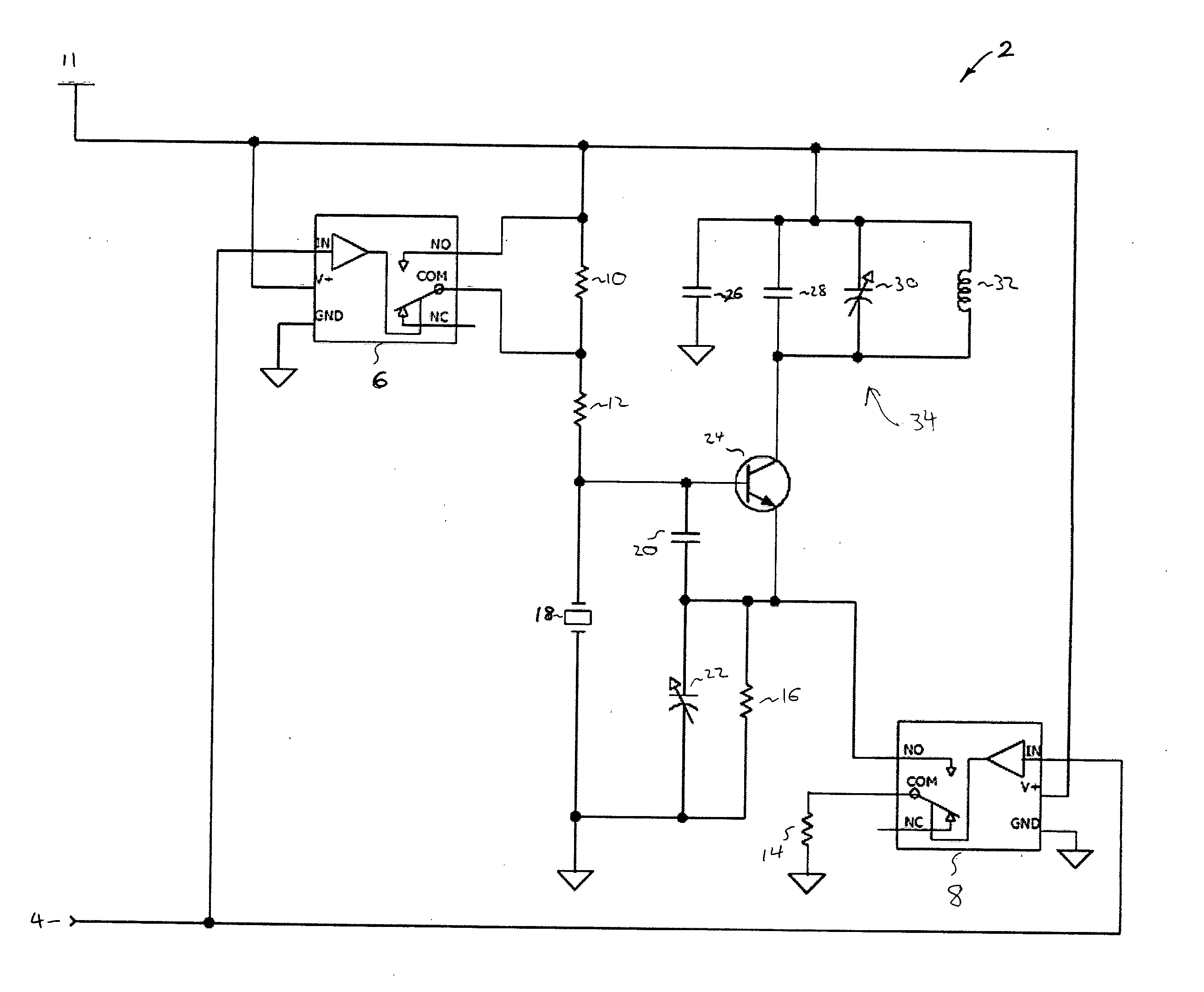
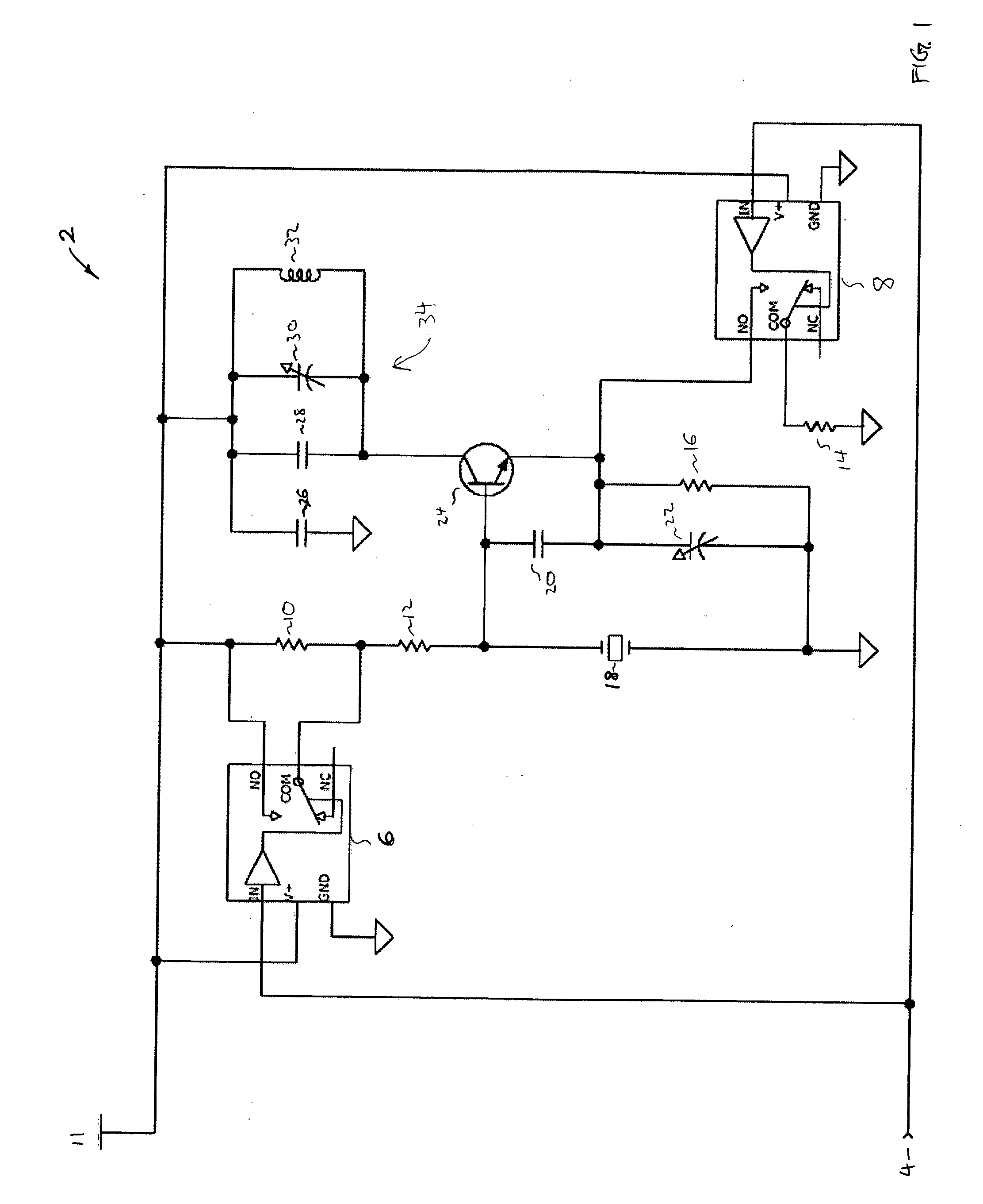
[0018]FIG. 1 is a simplified exemplary drawing of an oscillator according to an embodiment of the present invention. A signal 4 from a pulse generator (not shown) is input to an oscillator circuit 2 and sent to pins on switches 6 and 8. For example, the signal sent may be a pulsed signal to optimize the duration and battery life of the implantable device which contains the oscillator circuit. Of course, alternatives to a pulsed signal such as a continuous signal could also be used with the oscillator circuit 2. A variety of pulse durations can be used, such as an exemplary pulse duration of 5-10 μs separated by a gap of 500 μs between each subsequent pulse. By only operating the device during the duration of the pulse signal, the duty cycle of the oscillator can be greatly reduced. An exemplary duty cycle of 1% can be achieved compared to a duty cycle of 20% for a conventional implementation transitioning from an OFF position to a high current ON position within an oscillator.

[0019...


PUM


Abstract

An oscillator for use within an implantable medical device is provided. The oscillator includes a resonator and a first switch coupled to a first resistive network. The first resistive network provides a first electrical path through the first switch and a second electrical path not going through the switch. The oscillator additionally includes a second switch coupled to a second resistive network. The second resistive network provides a third electrical path through the second switch and a fourth electrical path not going through the switch. Furthermore, the oscillator includes a transistor, the base terminal coupled with the first resistive network and the resonator and the emitter terminal coupled to the fourth resistor. The second electrical path with the first switch opened has a substantially higher resistance than the first electrical path when the first switch is closed. In addition, the fourth electrical path with the second switch opened has a substantially higher resistance than the third electrical path when the second switch is closed.

Description

CROSS-REFERENCES TO RELATED APPLICATIONS [0001] NOT APPLICABLE BACKGROUND OF THE INVENTION [0002] The present invention is directed to implantable medical devices and their use in monitoring physiological parameters within a patient's body. More particularly, the invention provides a high stability fast start-up oscillator for implantable medical devices. The oscillator is maintained in a first current mode using a low current and switched to a second current mode utilizing a higher current. The transition between current modes provides for a reduced startup time without consuming significantly more power. However, it would be recognized that the invention has a much broader range of applicability. [0003] The use of implantable medical devices has become increasingly commonplace as an effective method of monitoring the state and condition of a living body. An implantable medical device can be implanted within a human or an animal to monitor physiological parameters about the patient...

Claims


Application Information

Patent Timeline
IPC IPC(8): H03B5/32
CPCH03B5/32H03B5/06
Inventor MOSESOV, OLEG
Owner DATA SCI INT
Why Eureka
Try Eureka