Handheld video transmission and display

a technology of which is applied in the field of hand-held video transmission and display, can solve the problems of noise and artificial spikes in the signal, the transmission of video signals with the full resolution and quality of televisions is still out of reach, and the quality of televisions is not acceptable, so as to reduce processing power and improve quality. the effect of quality and less draining

Inactive Publication Date: 2007-10-25
ZIN STAI PTE IN +1
View PDF50 Cites 47 Cited by
  • Summary
  • Abstract
  • Description
  • Claims
  • Application Information

AI Technical Summary

Problems solved by technology

However the transmission of video signals with the full resolution and quality of television is still out of reach.
A number of different approaches have been taken but each has resulted in less than acceptable results.
In the case where the image is generated based on sampled data, such as an ultrasound machine, there is often noise and artificial spikes in the signal.
Florescent or improper lighting may cause a solid background to flicker or appear grainy.
Such noise exists in the real world but may reduce the quality of the perceived image and lower the compression ratio that could be achieved by conventional methods.
These simple approaches by themselves have failed to achieve the necessary compression ratios.
This approach also has failed to achieve the necessary compression ratios.
These approaches require extensive computer processing and have failed to achieve the necessary compression ratios.
While these dictionary-based algorithms are popular, these approaches require extensive computer processing and have failed to achieve the necessary compression ratios.
However this loss results in certain blocks of the image being compressed such that areas of the image have a blocky appearance and the edges of the 8 by 8 blocks become apparent because they no longer match the colors of their adjacent blocks.
Another disadvantage of JPEG is smearing.
The true edges in an image get blurred due to the lossy compression method.
MPEG suffers from the same blocking and smearing problems as JPEG.
These approaches require extensive computer processing and have failed to achieve the necessary compression ratios without unacceptable loss of image quality and artificially induced distortion.
H.263 compresses in real time but does so by sacrificing image quality resulting in severe blocking and smearing.
These approaches require extensive computer processing and generally cannot be completed in real time.
However, the original iPod did not have a color display, a built-in camera, built-in speakers, built-in microphone or wireless communications.
Initially they had limited data bandwidth.
Hand held devices are limited in size and weight.
These size and weight limitation prevent handheld devices from having the electronic circuitry, processors, and batteries found in laptops and other larger computers.
These limitations have made it impossible to provide full frame, full motion video display or live transmission on handheld devices.
The existing, commercially available hand held devices have not been able to support live or streaming video for a number of reasons.
Uncompressed full-motion, full frame video requires extremely high bandwidth that is not available to handheld portable devices.
While MPEG is effective in desktop computers with broadband connections to the Internet, decoding and displaying MPEG encoded video is very processor intensive.
The processors of existing handheld devices are slower or less powerful than those used in desktop computers.
Further, the higher bandwidth wireless communications interfaces would also place a large strain on the already strained batteries.
Live video transmission and reception would be even more challenging.
For this reason, handheld device have not been able to transmit or receive streaming, or especially, live video.

Method used


Image

  • Handheld video transmission and display
  • Handheld video transmission and display
  • Handheld video transmission and display

Examples


Embodiment Construction

[0398]FIG. 1-Compression and Decompression Steps

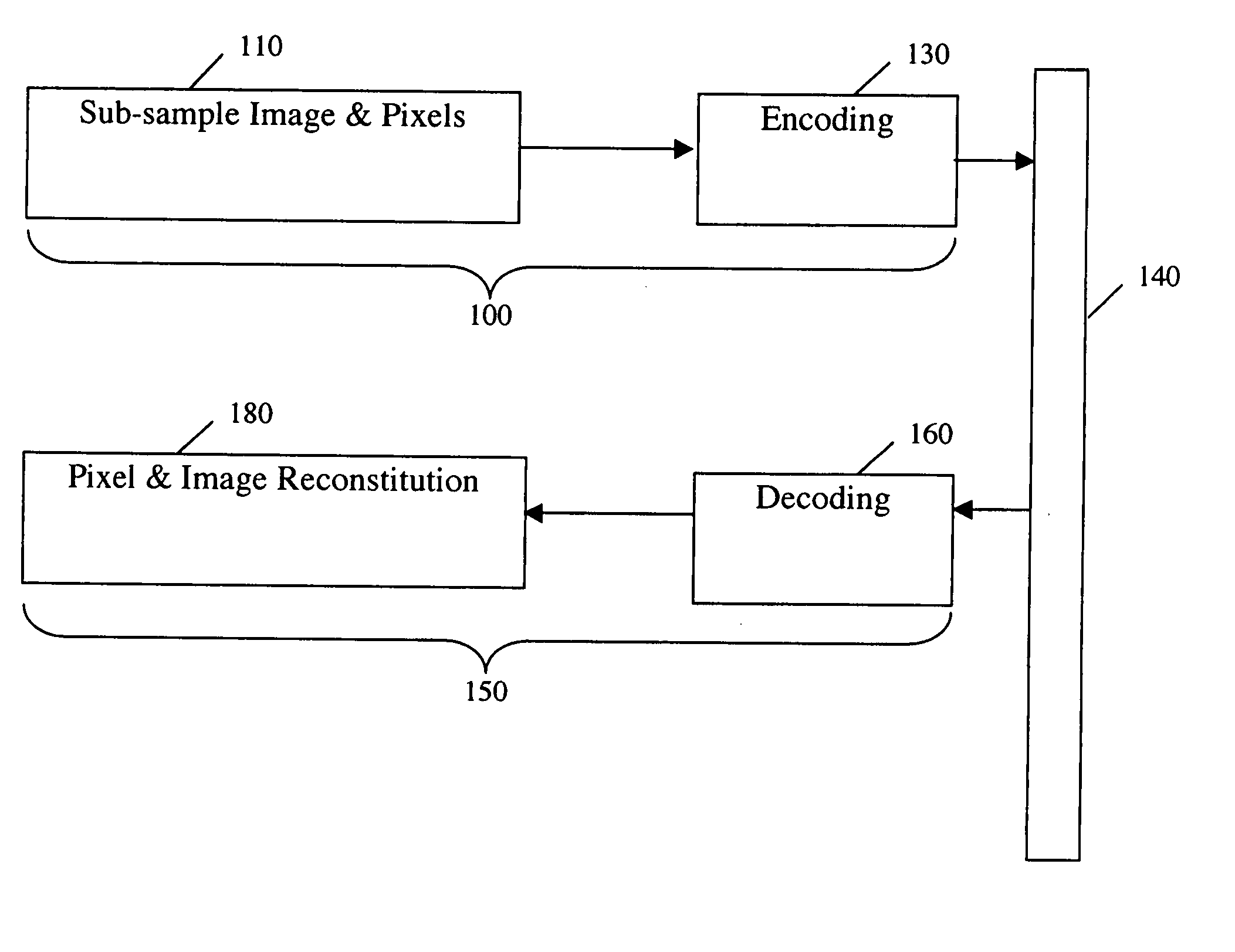
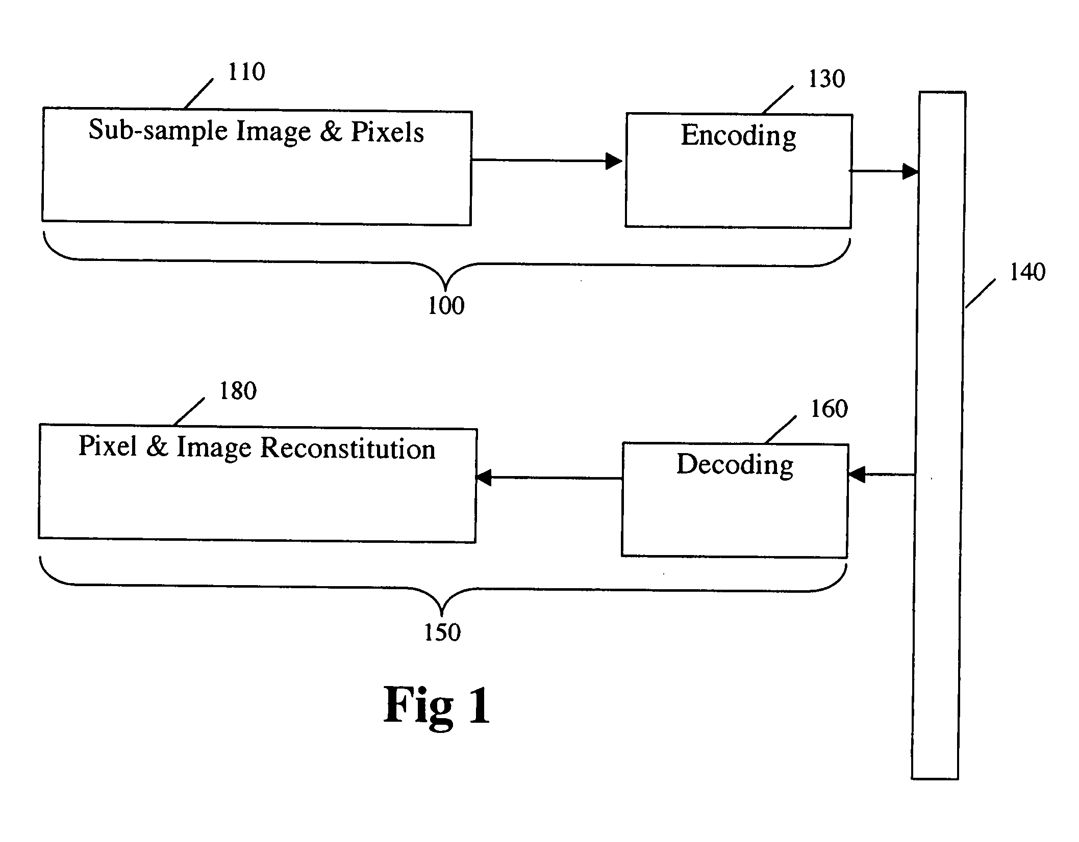
[0399]FIG. 1 illustrates a sequence of compression steps 100 and a sequence of decompression steps 150 of the present invention. The compression steps 100 comprise a sub-sampling step 110 and an encoding step 130. After completion of the compression steps 100, a stream of encoded data 140 is output to either a storage medium or a transmission channel. The decompression steps 150 comprise a decoding step 160 wherein the stream of encoded data 140 is processed and an image reconstitution step 180.

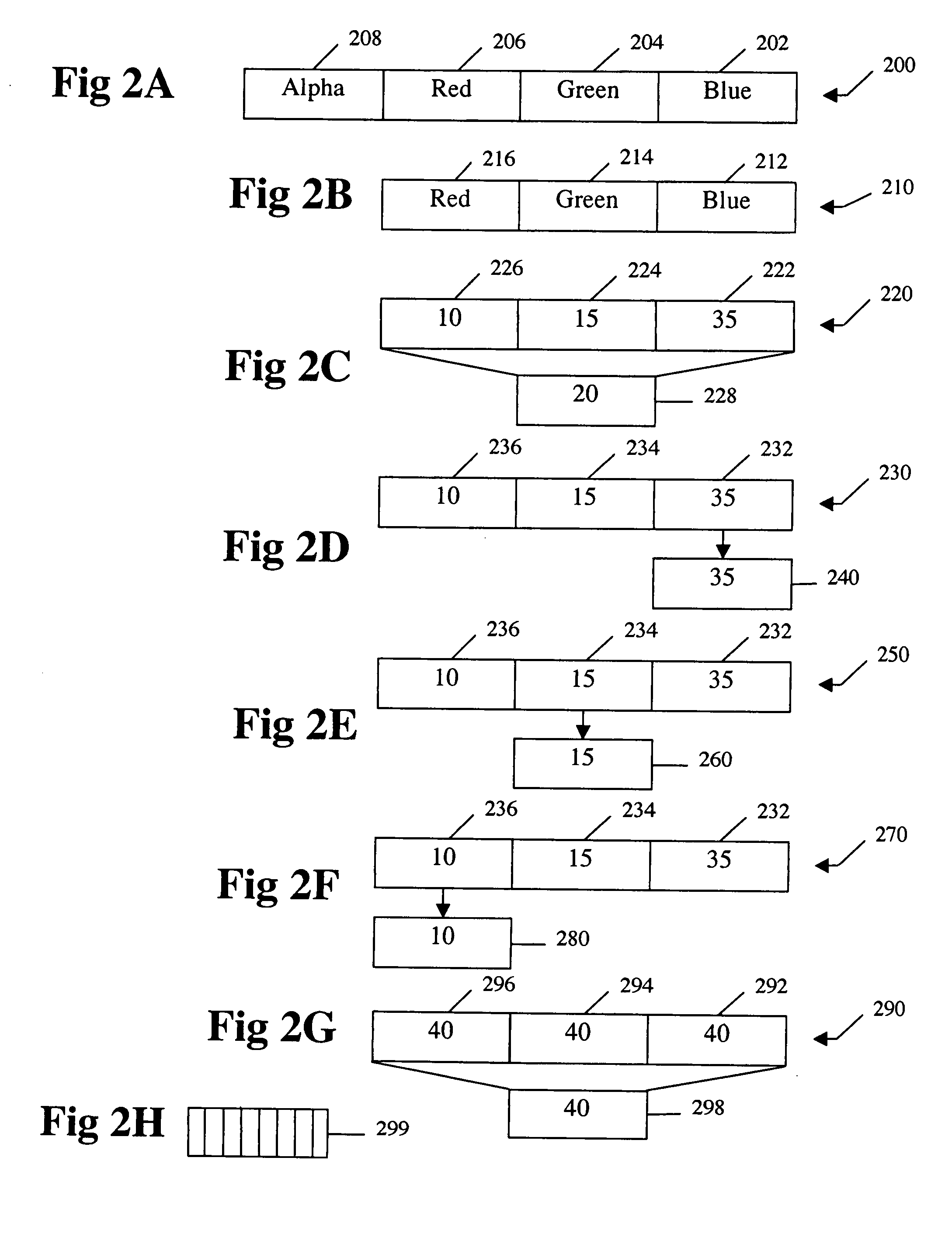
FIGS. 2A to 2H Selecting Pixel Values for Encoding

[0400]FIGS. 2A to 2G illustrate alternatives for selecting a pixel value for encoding. The sub-sampling step 110 (FIG. 1) includes sub-sampling of a pixel value to obtain a variable selected number of bits.

[0401] Video digitizing hardware typical has the options of storing the pixel values as a 32 bit pixel value 200 or a 24 bit pixel value 210, shown in FIG. 2A and FIG. 2B, respectively. The...


PUM


Abstract

A handheld, wireless video receiver that receives compressed video, decompresses the compressed video, displays the decompressed video. The receiver is part of a system comprising methods, medium, and handheld, wireless devices which compress, enhance, encode, transmit, decompress and display digital video images in real time. Real time wireless videoconferences connect multiple handheld video devices. Real time compression is achieved by sub-sampling each frame of a video signal, filtering the pixel values, and encoding. Real time transmission is achieved due to high levels of effective compression. Real time decompression is achieved by decoding and decompressing the encoded data to display high quality images. The receiver can alter various setting including but not limited to the format for the compression, image size, frame rate, brightness and contrast. A zoom control can be used select a portion of interest of video being transmitted or being played back. The receiver may also have a touch sensitive display screen providing controls for video display and mobile telephone operation.

Description

CROSS-REFERENCE TO RELATED APPLICATIONS [0001] This application is a continuation of co-pending U.S. patent application Ser. No. 11 / 262,106, filed on Oct. 27, 2005, published Jun. 1, 2006, as U.S. patent application publication 2006 / 0114987, entitled “HANDHELD VIDEO TRANSMISSION AND DISPLAY,” which hereby is incorporated by reference. [0002] U.S. patent application Ser. No. 11 / 262,106 is a continuation in part of co-pending U.S. patent application Ser. No. 09 / 467,721, filed on Dec. 20, 1999, and entitled “VARIABLE GENERAL PURPOSE COMPRESSION FOR VIDEO IMAGES (ZLN)”, now U.S. Pat. No. 7,233,619, which hereby is incorporated by reference. [0003] This application and application Ser. No. 09 / 467,721 claim priority under 35 U.S.C. § 119(e) of U.S. provisional application Ser. No. 60 / 113,051, filed on Dec. 21, 1998, and entitled “METHODS OF ZERO LOSS (ZL) COMPRESSION AND ENCODING OF GRAYSCALE IMAGES”, which hereby is incorporated by reference. [0004] My U.S. patent application Ser. No. 09...

Claims


Application Information

Patent Timeline
Patent Type & Authority Applications(United States)
IPC IPC(8): H04N7/14
CPCH04N7/142H04N7/147H04N7/148H04N7/15H04N19/59H04N19/132H04N19/136H04N19/184H04N19/93H04N2007/145H04N23/62
Inventor ROMAN, KENDYL ALLEN
Owner ZIN STAI PTE IN
Why Eureka
Try Eureka