Light Emitting Diode Packages

Active Publication Date: 2007-10-25
CREELED INC
View PDF30 Cites 162 Cited by
  • Summary
  • Abstract
  • Description
  • Claims
  • Application Information

AI Technical Summary

Benefits of technology

[0008] As discussed below, among its several aspects, the present invention recognizes the desirability of both increasing brightness and passively controlling heat dissipation of heat generated by powered LEDs and addresses a variety

Problems solved by technology

When this emitted light strikes a diffuser, such as back lighting a curtain or a shield covering an LED light package, for example, yellow rings around a concentration of white light may be visible to the human eye, causing a degradation of color uniformity.
Several disadvantages of this conventional technique includ

Method used


Image

  • Light Emitting Diode Packages
  • Light Emitting Diode Packages
  • Light Emitting Diode Packages

Examples


Example

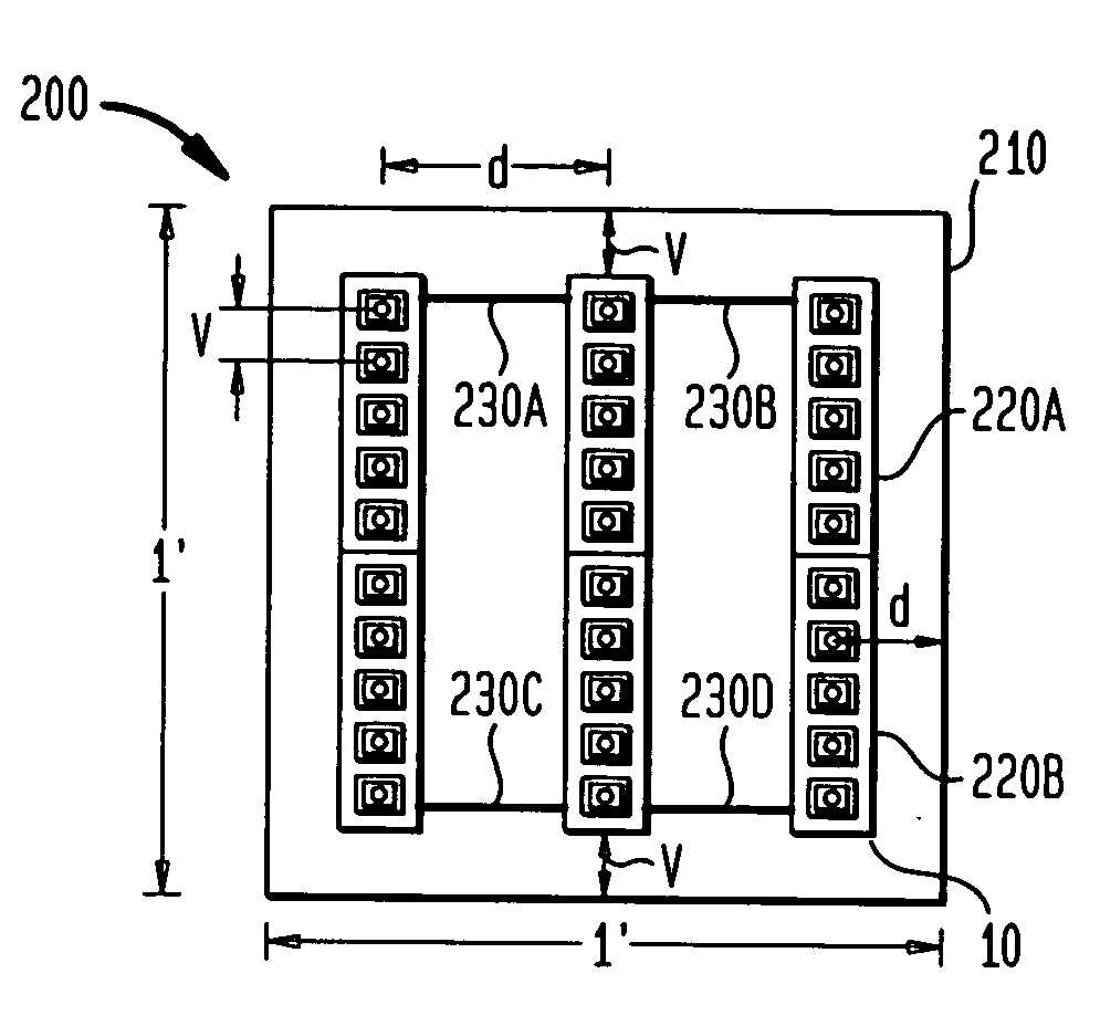
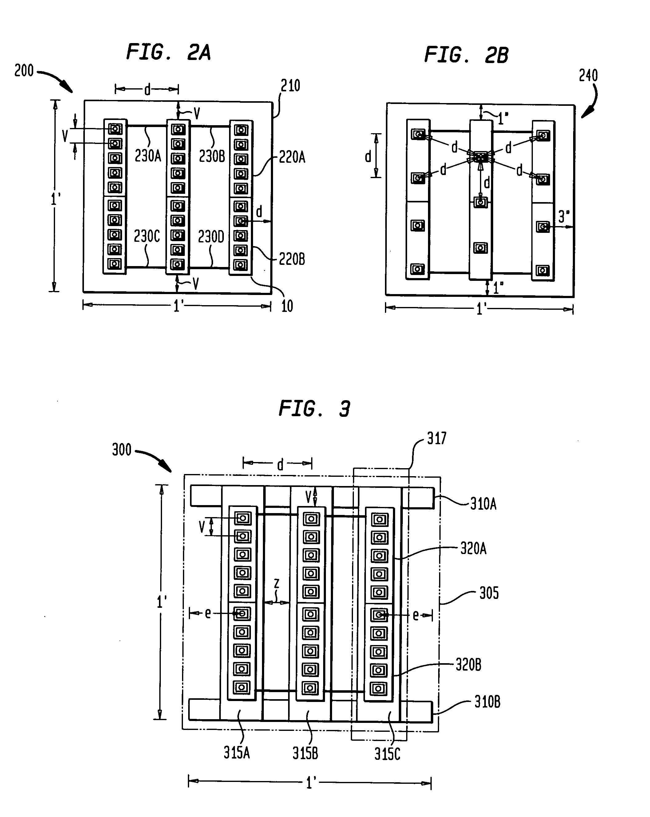
[0023]FIG. 2A shows a top view of a 1 foot×1 foot light emitting diode (LED) lighting package 200 in accordance with the present invention. The LED lighting package 200 includes a backing 210 of thermally conductive material such as aluminum. Backing 210 as shown in FIG. 2 is a planar sheet of aluminum with a thickness of approximately 1 / 16 inch. It should be noted that other backing constructs may provide additional heat dissipation properties and can be employed in similar arrangements as backing 210. For example, the patent application entitled “Light Emitting Diode Lighting Package with Improved Heat Sink” concurrently filed with this application addresses additional backing structures and is incorporated by reference herein in its entirety.

[0024] Also, it is recognized that other thermally conductive materials such as ceramics, plastics, and the like may be utilized. Aluminum is presently preferable because of its abundance and relatively cheap cost. The LED lighting package 2...


PUM


Abstract

Lighting packages are described for light emitting diode (LED) lighting solutions having a wide variety of applications which seek to balance criteria such as heat dissipation, brightness, and color uniformity. The present approach includes a backing of thermally conductive material and two or more arrays of LEDs attached to a printed circuit board (PCB). The PCB is attached to the top surface of the backing and the two or more arrays of LEDs are separated by a selected distance to balance heat dissipation and color uniformity of the LEDs.

Description

FIELD OF THE INVENTION [0001] The present invention relates generally to improvements in the field of light emitting diode (LED) packages, and, in particular, to methods and apparatus for achieving color uniformity, desired brightness levels, and passive dissipation of heat when LEDs are arranged to address the varied requirements of different lighting applications. BACKGROUND OF THE INVENTION [0002] As illustrated by FIGS. 1A, 1B and 1C, a common prior art LED mounting arrangement results in a substantial portion of the light output going upwardly in the direction of a normal to the top surface of a semiconductor photonic chip 12 as seen in FIG. 1B. As seen in FIG. 1A, a top view of an LED 10, the semiconductor photonic chip 12 is mounted on a substrate 14 which is in turn mounted on a bonding pad 16. The chip 12 is encapsulated beneath an optical lens 18 which focuses the light emitted by the chip 12. [0003]FIG. 1B shows a side view of LED 10 with a plurality of light rays relativ...

Claims


Application Information

Patent Timeline
IPC IPC(8): F21W101/02H01L33/48F21K99/00F21W107/10H01L33/60H01L33/64
CPCF21K9/00F21V29/004F21Y2101/02H05B33/0848F21Y2105/001H05B33/0821F21Y2103/003F21Y2105/10F21Y2103/10F21Y2115/10H05B45/14H05B45/40F21V29/70
Inventor VILLARD, RUSSELL G.
Owner CREELED INC
Why Eureka
Try Eureka