Fluid material dispensing syringe

a technology of fluid material and syringe, which is applied in the field of syringe, can solve the problems of high fluid pressure, potential danger of injecting anesthetic in the bloodstream, and limited maximum fluid pressure, and achieve the effect of increasing the rate of local anesthetic delivery

Inactive Publication Date: 2007-10-25
HOHLFELDER INGRID ELAINE +3
View PDF99 Cites 37 Cited by
  • Summary
  • Abstract
  • Description
  • Claims
  • Application Information

AI Technical Summary

Benefits of technology

[0026] In another embodiment of the invention, a computer program is embodied on a computer readable medium and executable by a microprocessor for controlling a device to deliver a local anesthetic into a patient through a needle, the computer program product comprises computer instructions for executing the steps of: generating a first at least one signal to operate the device to deliver the local anesthetic at a first predetermined rate for a first predetermined time period; transmitting the first at least one signal to the device to operate the device to deliver the local anesthetic at a first predetermined rate for a first predetermined time period; generating a second at least one signal to operate the device to deliver the local anesthetic at a second predetermined rate for a second predetermined time period; and, transmitting the second at least one signal to the device for the device to operate at the second predetermined rate for the second predetermined time immediately upon completion of the first predetermined time period. In one embodiment, the second predetermined rate is in the range of 0.005-0.02 cc / sec. In another embodiment, the second predetermined time is in the range of 30-240 seconds. In a preferred embodiment, the step of generating a second at least one signal further comprises the steps of receiving a user signal corresponding to an injection type selected by a user; determining a delivery rate and delivery time based on the injection type received in the user signal; and, generating the second at least one signal to operate the device to deliver the local anesthetic at the delivery rate for the delivery time based on the selected injection type. The computer program may include instructions for executing the steps of calculating a rate of delivery of the local anesthetic through the needle, and displaying the calculated rate of delivery of the local anesthetic. The program may also include instructions for calculating an elapsed time of delivery of the local anesthetic through the needle and displaying the elapsed time of delivery of the local anesthetic; or, calculating a volume of the local anesthetic delivered through the needle and displaying the volume of delivered local anesthetic. The computer program may also include instructions for receiving a user signal corresponding to a load command selected by a user; generating a third at least one signal to operate the device to position components of the device to receive a cartridge storing the local anesthetic; and, transmitting the third at least one signal to the device for loading the local anesthetic cartridge in the device. It may also include instructions for receiving a user signal corresponding to an unload command selected by a user; generating a third at least one signal to operate the device to position components of the device to remove a cartridge storing the local anesthetic; and, transmitting the third at least one signal to the device for unloading the local anesthetic cartridge from the device. In another embodiment, the program includes instructions for receiving a user signal corresponding to a double command selected by a user; generating a third at least one signal to operate the device to increase the rate of delivery of the local anesthetic to twice the rate of delivery being provided by the device; and, transmitting the third at least one signal to the device for increasing the rate of delivery of the local anesthetic by the device.

Problems solved by technology

A rapid injection into the periodontal ligament space, which has limited capacity to absorb or distribute fluid, will result in high fluid pressure.
In the latter case, the maximum fluid pressure will ultimately be limited by the pressure (force) attainable with the injection device.
(Injecting the anesthetic in the bloodstream is potentially hazardous.)
Another drawback is that various designs of gripping members either pull out of the carpule seal prematurely, or are not easily removed after injection is completed.
A drawback of this method is that the carpule seal is not consistently retracted.
Another drawback is that the syringe plunger seal must be periodically cleaned, lubricated, or replaced.
It has been found in laboratory tests, that none of these method work reliably, failing in one or more of the following ways: did not penetrate certain brands of carpules with high durometer rubber plungers; requiring excessive user effort or skill; pulling out of the carpule plunger and therefore failing to create an aspiration vacuum; and / or, becoming loaded with the silicone lubricant used on these carpule plungers, and then failing to grip the plunger.
Further, previous dental anesthesia syringes have had several problems in their operation: only a single injection rate for all procedures; only crude feedback on the amount of anesthetic injected; no feedback for the elapsed time of injection; does not allow the practitioner to speed-up the injection rate.
One device, described in U.S. Pat. No. 5,690,618, addressed some of these issues, but exhibited other problems: very complex to use, requiring the clinician to program various rates and times for each injection; and, no feedback for the elapsed time or cumulative volume of injection.

Method used


Image

  • Fluid material dispensing syringe
  • Fluid material dispensing syringe
  • Fluid material dispensing syringe

Examples


Embodiment Construction

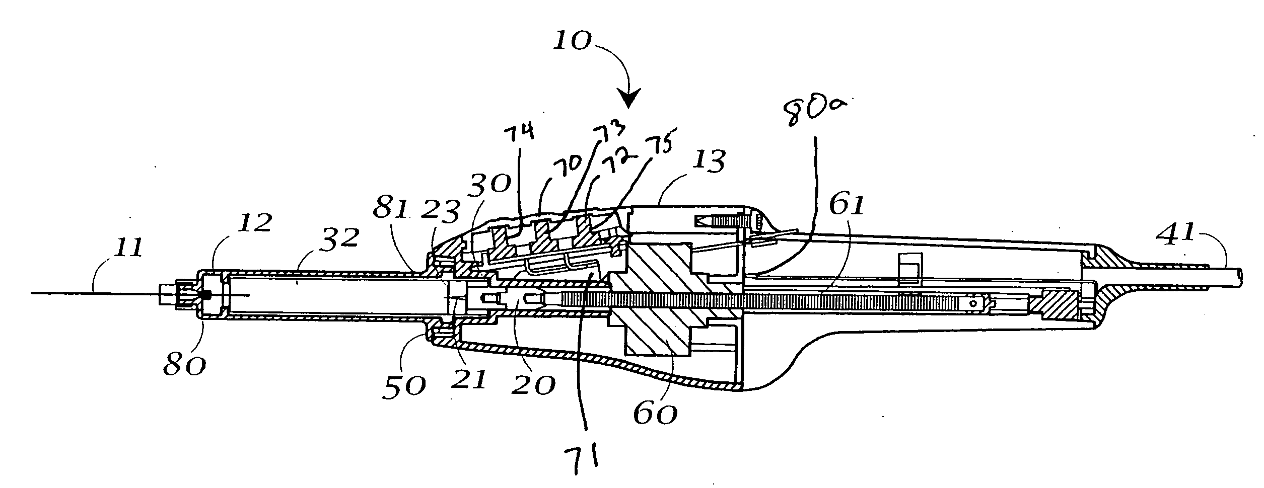
[0045] An exemplary computer controlled syringe, embodying the concepts of the present invention, is generally shown by the number 10 on the attached drawings. Syringe 10 has a dispensing tip 11 fluidly affixed to a carpule holder 12, which carpule holder 12 is releasably affixed or connected to a syringe power unit 13.

[0046] Carpule holder 12 is initially (that is, prior to dispensing) loaded with the material to be dispensed (not shown) by any conventional means, such as a conventional carpule or the like. Any carpule capable of being dispensed by the action of a physically engaging plunger (to be discussed below) is within the scope of the invention. Carpule holder 12 may be affixed to syringe 10 by any conventional means, including for example, bayonet connector 50 at one end of carpule holder 12. At it other end, carpule holder 12 is preferably provided with means to affix or removably affix the dispensing tip 11. In the case of the use of syringe 10 to dispense a dental anest...


PUM


Abstract

A dental syringe (10) has a needle (11) affixed to a carpule holder (12), which carpule holder (12) is affixed to a power drive unit (13). A harpoon (20) is provided to affix the drive unit to the carpule plunger (32). The harpoon (20) is made of stainless steel or other hard, corrosion resistant, sterilizable, material. Harpoon 20 has a unique barb geometry and hardened, knife-like, edges (21). The syringe (10) may operate to divide the delivery of anesthesia into two phases. According to the method, during the first about 10 seconds of the injection, anesthetic is delivered at an extremely slow rate to maximize patient comfort. The injection rate then automatically increases to the preprogrammed rate associated with the injection type selected.

Description

RELATED APPLICATIONS [0001] This application is a Continuation application of U.S. patent application Ser. No. 09 / 974,361 (Case MID-38 ABC) filed Oct. 10, 2001, which claims the benefit from Provisional Application No. 60 / 238917 filed Oct. 10, 2000.TECHNICAL FIELD [0002] The present invention is directed toward a syringe for dispensing a fluid material such as a dental anesthesia. The invention provides an electronic programmable device indicated for the injection of local anesthetics for infiltration and nerve block anesthesia administered prior to, or in conjunction with, dental procedures, and the like. BACKGROUND OF THE INVENTION [0003] Syringes, of any type, are essentially positive displacement pumps which generate a flow of liquid. While the present description may employ terms denoting an anetsthetic, including the word “anesthesia” or the like, it is to be understood that the present invention has application to the injection of any fluid into a patient. For convenience, th...

Claims


Application Information

Patent Timeline
Patent Type & Authority Applications(United States)
IPC IPC(8): A61M5/145
CPCA61C5/062A61C19/08A61M5/482A61M5/172A61M5/24A61M5/14566A61C5/62
Inventor HOHLFELDER, INGRID ELAINEZDANOWSKI, CHESTER L.PAPANEK, TOMCHOU, TAN-CHENG
Owner HOHLFELDER INGRID ELAINE
Why Eureka
Try Eureka